
Pages: [ 1 ] [ 2 ]
It's time to see the scheme of the shocker. It is very simple and I think it will not cause problems with understanding. A burning igniter is charged through the bridge, and a combat one is charged simultaneously through additional diodes. These diodes are needed so that the capacitors do not create one circuit, otherwise it would be necessary to wind a separate winding of the trance and the second bridge which is very tense - isolating the trance will have to be no worse than the output and the dimensions will be larger. At some difference in the time of the charge, which in theory is present with such an option, you can safely ignore it, because In practice, it simply does not exist. Hence, only one restriction follows, the capacitors must be the same. What really does not bother us.
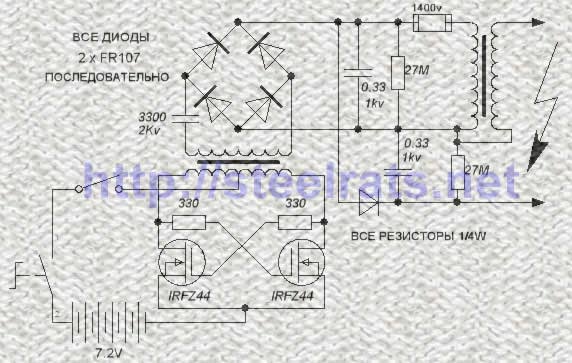
All the details are not particularly scarce, they can be freely ordered or simply bought at the market. The most critical are conduits and a discharger, I advise you to undo it and find exactly what is listed in the list of details. The size of the shocker and the quality of his work depend on them. All the rest can be put that will fall under the arm. For the converter are suitable almost any transistors from IRFZ24 and ending with IRL2505. The resistors are also uncritical and can differ in one direction or the other. The 3300 peak capacitor is needed to limit the current surge at the time of launch, i.e. To protect the inverter. When using rather powerful transistors (IRFZ44 +) it can not be set.
There is one interesting feature in the work of this scheme that some could already notice. Namely, when the contacts are short-circuited, for example, when the two electrodes are directly contacted with the skin, the correct operation of the shocker is broken, because The combat conder does not have time to recharge to the desired voltage. In this case, this jamb is not as important as in multiplayer shockers, because The voltage on the capacitor is only about 1000 volts, which is not enough even for punching a thin tank top. Therefore, for the sake of simplicity and cheaper construction, this fact was not paid attention. But still, if you are going to go to war with nudists :-D THEN YOU NEED TO PUT THE SECOND DISCHARGE sequentially with any of the output electrodes of the shocker!
Now a little about the constructive composition of the device. The whole circuit, with the use of these parts, is placed on a board sized 40 * 45mm. Batteries are 6 pieces of NicD size 1/2 AA, i.e. Twice shorter than conventional fingers, with a capacity of 300 mAh. Which corresponds to a power of about 15W. They are sold as spare for radiotelephones in the form of blocks of 3 or 4 pieces. The cost in the area of hundreds of wooden per block ;-) Thus, the entire shocker can be made the size of a pack of cigarettes.
The assembly sequence is as follows. For starters we refuse payment, because Love in the process will have to re-solder these or other parts and it will inevitably go there ... We take the radiator, for example from the BP computer and put transistors on it. The radiator must either have insulating spacers or then 2 separate radiators are needed so that they do not touch each other .. We screw them there and we solder all the rest directly on the weight. So the initial layout should look like a pile of rubbish on your desk  Do not forget to fix HV pins at the right distance (for the beginning no more than 15mm) otherwise the transformer and all the rest behind it also has our burn.

Turn on the device. The food should be taken from those Akum who will go to the device later, all kinds of power supplies and other sources will not do! In principle, the settings do not require a shocker and should be earned immediately. The question is how it will work. With these Akum, the discharge frequency is about 35 hertz. If it is smaller, then maybe two options, or the transformer is wound up badly, or you used other transistors and you need to pick up resistances at 330 ohms.
We look at the datasheet for the trance you need, look for the line "INPUT CAPACITANCE", the larger the number, the less resistance there is and vice versa. For example, for IRFZ44 it can be 1k, and for IRL2505 it can not be more than 240 Ohm. Selecting the optimal frequency of discharges ... Next, start to build the output contacts to the estimated distance that you need (for example, I have 25mm). If everything is ok, we're bred for another centimeter! And in this state do the test for 5 seconds. If everything is ok, we return the previous distance. This stock should like to be present, tk. Air breakdown depends on many factors such as humidity, pressure, etc., so if the distance is "at the limit", at one point the whole construction will go to nothing. For the same reason, 2 diodes are used everywhere instead of one, although with one everything (like) works perfectly.
If everything worked as it should, you can boldly weld parts into a pay and move on to the next stage ...
Since we can not stamp parts from plastic at the factory, and few people have the opportunity to use the factory building, there is only one thing - EPOXICS. The process is certainly painstaking, but it has a number of advantages. As a result, a monolithic block is obtained, which is not afraid of blows, water ingress, absolutely reliable in the electric plane. For the production you will need the epoxy itself, take it a lot, thin cardboard from the box, glue gun and some other little things ...
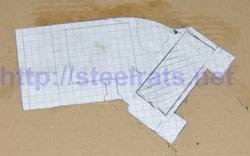
The process begins with the cutting out of the base of cardboard, i.e. "view from above". For etogo it is very convenient to use a notebook sheet on which to pre-mark the plan as well as what will be located, then paste it on a cardboard and cut it out ...
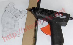
Next, prepare strips of cardboard about 3 cm wide, and also an adhesive gun.


Now your task is to glue the base around the perimeter with these strips. The process is rather complicated. For folding the cardboard it is convenient to use pliers with a long nose or tweezers .. It is necessary to glue on the outside, while checking the tightness of the seam.
Arrange all the main parts inside the enclosure to evaluate their internal layout. At this stage, you need to determine where the switch and start button will be located As well as a slot for charging the battery.
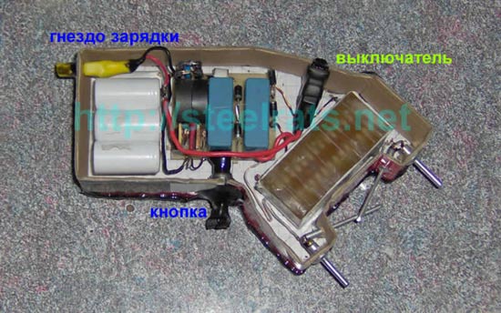
Apply heat shrinkage. It is very convenient to use it for some utaplivaniya protruding elements inside. Take into account that after pouring the treatment will follow and somewhere 2-3mm will be removed at the sides due to the cardboard. Also heat shrinkage allows to achieve better tightness - in the photo it is visible that from the outside it is closed (it is enough to squeeze with tweezers while it is hot). At the same stage, you need to connect all the parts together and check the operation of the shocker in this state. As combat and protective electrodes I used aluminum rivets, thicker and thinner respectively. Inside, aluminum is a steel rod, so soldering should not be a problem, but it is very convenient to use acid.
Fill it! There is nothing to explain here, but note that the epoxy has the property to penetrate everywhere where it is not necessary, so check the tightness before refilling. Checked? Now again. After that you can proceed ...
The processing step. After 6-8 hours, when the epoxy is firmly seized, it still remains soft enough. At this point, you can cut off the excess with a mounting knife, giving the shocker a convenient shape to hold in your hand. This will not save you the need to do further processing with emery and sandpaper, but will save a lot of nerve cells ;-) After treatment, the body can be covered with a thread of varnish, for example a cap.
And here is the result! After all you can be pleased looking at this thing. Now you can bite the protective electrodes to the desired length if you have not done so yet, and go!

So, the shocker is made, loudly pops and makes an impression on others ;-) But how can you really check the degree of his anger? In the beginning, we said that it depends on the current in the pulse that the shocker gives. So we'll look for him ;-) Below you see a comparison of the discharge from the usual gearchle and our device:
It is seen that the discharge is much thicker, it has a characteristic yellow color and flashes at the edges, which indicates a large current. How big? Let's conduct a simple test. Take a conventional mains fuse of 0.25A and place it between the contacts of the shocker, so that there is no direct contact. The fuse will burn. This means that the output current exceeds 250 mA !!! Compare with the shares of a mielamper in an ordinary shocker It is clear that in real terms, because of the resistance of body tissues, this current will be less, but it will be 10 times greater than the values for ordinary civilian and even police models!
Pages: [ 1 ] [ 2 ]

Comments
Commenting on, remember that the content and tone of your message can hurt the feelings of real people, show respect and tolerance to your interlocutors even if you do not share their opinion, your behavior in the conditions of freedom of expression and anonymity provided by the Internet, changes Not only virtual, but also the real world. All comments are hidden from the index, spam is controlled.