
How to make a transformer Tesla.
The self-made Tesla transformer
The simplest Tesla transformer consists of two coils without a common core. The primary winding has several (3-10) turns of thick wire. The secondary (high-voltage) winding contains much more turns, about 1000. Tesla transformers have a transformation ratio of 10-50 times higher than the ratio of the number of turns of the secondary winding to the number of turns of the primary. The output voltage of the Tesla transformer can reach several million volts. This voltage at resonance frequency can create impressive electrical discharges in the air, which can have a length of many meters. The result of one experiment with such a transformer was a burned-out power plant generator in Colorado Springs, which supplied current for the primary winding. Nikola Tesla repaired the generator and continued the experiment, during which it was proved the possibility of creating a standing electromagnetic wave. So, the most difficult thing about the Tesla transformer is the power circuit for the primary winding of the transformer.

It's very easy to make a Tesla coil, but to make it so that it's not embarrassing to show it, nevertheless, it's very expensive and time consuming.
We take any high voltage source (MINIMUM 1.5kV and in general get used to, that now volts do not exist, there is only kV, and 1.5kV is as small as 1.5V in ordinary life) it is better to take at least 5 kV, we connect it to any capacitor at (If the capacitance is too large, then a diode bridge will also be needed, but to begin with, it is better to experiment with small containers), then through a spark gap (two wires wound with electrical tape, so that their bare ends look in one direction, bending the wire of the wire Adjust the gap set at the breakdown at a voltage slightly above the source voltage (the current is variable, so that the peak voltage is higher than the rated voltage), connect this case to the primary winding of the coil (for our parameters it is better to take 5-6 turns.) For a secondary winding, There will be 150 turns (you can wrap it around a regular cardboard tube) and if you did everything correctly, you will get a 1 cm discharge if you bring the coil leads closer and a rather noticeable crown, if you dilute them. Yes, do not forget one lower terminal of the secondary winding is good for grounding.
For Tesla, which is not a shame to show, it is already necessary to sweat:
A) The input voltage should be a minimum of 6kV, otherwise the spark will not work stably (the setting will be lost).
B) The spark plug must be made of massive pieces of copper, and their hard fixation in the desired position is desirable.
C) The power at the input is not lower than 50W, but better than 100+.
D) The capacitor and the primary winding must form an oscillatory circuit in resonance with the secondary winding. The secondary winding can have many multiple resonances (for example, in our scheme it resonates at 200, 400, 800 and 1200kHz, which is why I do not know why, but it is tested experimentally on precise equipment), and some are weaker (the first is not necessarily the most Strong) and they depend on the location of the primary winding. How to determine these frequencies without a frequency generator I do not know - you will have to use the "scientific poke" method, rewinding the primary winding and changing the capacity of the capacitor.
C) It will also require either a relatively small capacitance of the capacitor (so that it can be charged to a high voltage by alternating current) or a diode bridge of rectification of current (with the bridge somehow calmer - you can connect any capacitor, but there is a resistor for its discharge, after turning off the power Or in its manual short, or it VERY painfully beats current).
D) The primary winding must be well insulated from the secondary winding, otherwise it will break into it. Secondary winding should also have good interturn isolation, otherwise from each scratch on the varnish there will be a crown, or in general the whole coil will glow.
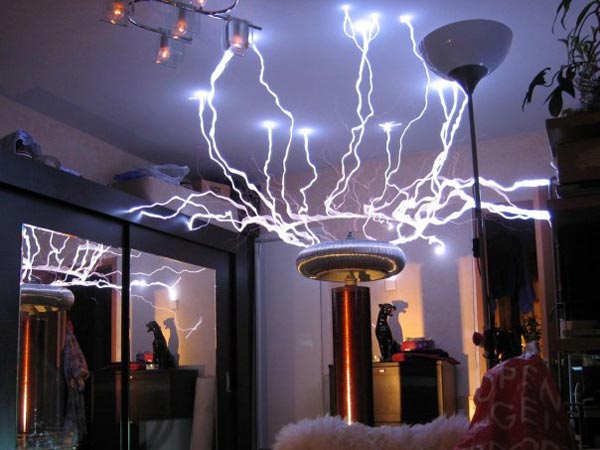
And now let's talk about how to make a Tesla coil with your own hands , similar to the one depicted at the very top!
1. Tesla transformer scheme
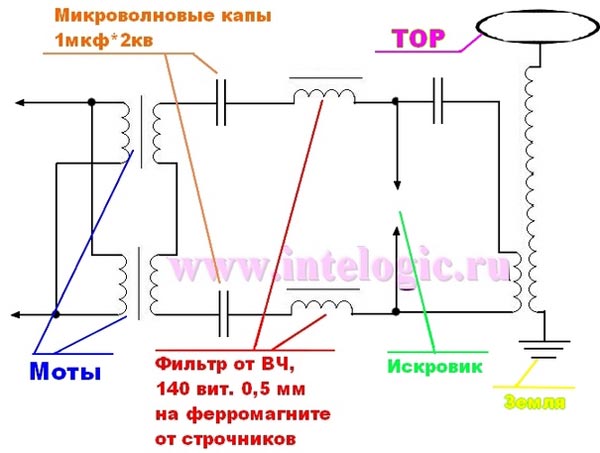
As you can see, this scheme has a minimum of elements, which does not make our task any easier. After all, so that it works it is necessary not only to assemble it, but also to set it up! Let's start in order:
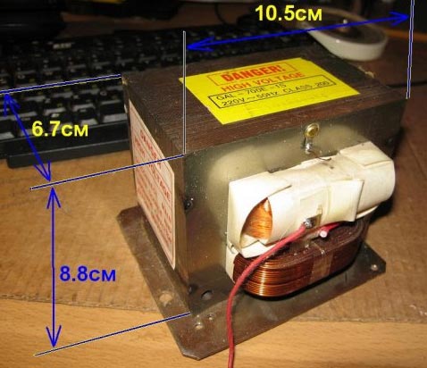
MOTES: such a transformer is in the microwave. It is a conventional power transformer with only one difference, that its core operates in a mode close to saturation. This means that, despite its small size, it has a power of up to 1.5 kW. However, there are also negative sides to this mode of operation. This is also a large no-load current, about 2-4 A, and a strong heating even without a load, I'm silent about the heating with the load. The normal output voltage of the ILO is 2000-2200 volts at a current of 500-850 mA.
At all МОТов the primary is wound up below, secondary from above. This is done for good insulation of the windings. On the secondary, and sometimes on the primary, a winding of the magnetron is wound, about 3.6 volts. And between the windings you can see two metal jumpers. These are magnetic shunts. Their main purpose is to close a part of the magnetic flux created by the primary and thus limit the magnetic flux through the secondary and its output current at a certain level. This is due to the fact that in the absence of shunts in the short circuit in the secondary (with the arc) current through the primary increases many times and is limited only to its resistance, which is already very little. Thus, shunts prevent the trance from quickly overheating when the load is connected. Although the ILO warms up, but in the stove put a nehily fan for its cooling and it does not die. If the shunts are removed, the power given by the trance increases, but overheating occurs much faster. Shunts from imported MOTs are usually well filled with epoxy and not easily removed. But it is still desirable to do this, the drawdown under load will decrease. To reduce the heat, I advise you to shove the ILO into the oil.
ATTENTION!!! ILO IS DANGEROUS !!! VOLTAGE ON SECONDARY WINDING IS DEATH !!! OBSERVE CARE AT WORK WITH IT !!!
The voltage, although small in comparison with the line, but the current strength, a hundred times greater than the safe limit of 10mA will make your chances of staying alive almost equal to zero.
I can upset some people by reporting that the ILO, although an ideal power source for Tesla coils (small, powerful, does not suck from HF as NST), but its price ranges from 600 to 1500 and above rubles. In addition, even if you have such money, you will have to run around the radio market and shops in search of it. Personally, I never found an imported ILO, not new, not second-hand. But I found the ILO from the Soviet microwave electronics. It has much larger dimensions than imported ones and works like a normal trance. It is called TV-11-3-220-50. Its approximate parameters: power about 1.5 kW, output voltage ~ 2200 volts, current strength 800 mA. Nice parameters. And on it, except primary, secondary and incandescent, there is also a winding for 12 V, just to power the cooler on the sparkle.
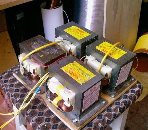
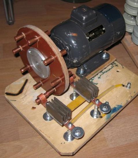
The author of our Tesla used these motives:
And further:
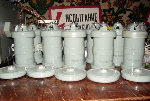
Caps: High-voltage ceramic capacitors (series K15U1, K15U2, TGK, CPC, K15-11, K15-14-for high frequency settings are implied!) The most difficult thing is to find them. Introducing a photo sketch  ))
))
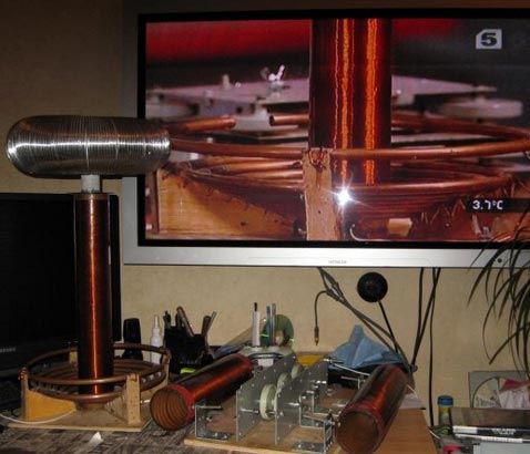
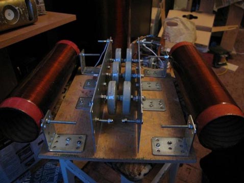
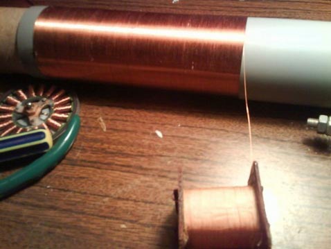
Filter from HF: two coils, respectively, performing the function of filters from high-frequency voltage. In each 140 turns of copper lacquered wire 0.5 mm in diameter.
Very well distinguishable in this figure:
And further:
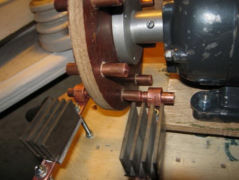
Sparkle: Sparkle is needed to switch power and excite oscillations in the circuit. If there is no treasure in the scheme, then there will be food, but there is no hesitation. And also the power unit starts to siphonize through the primary - and this short circuit! While the spark is not closed, the batteries are charged. As soon as it closes, oscillations begin. Therefore, they put ballast in the form of chokes - when the spark is closed the throttle prevents the current from flowing from the power supply unit to be charged itself, and then, when the discharger opens, charges the kapi with a double anger. Yes, if the socket had 200 kHz, the surge arrester would naturally not be needed.
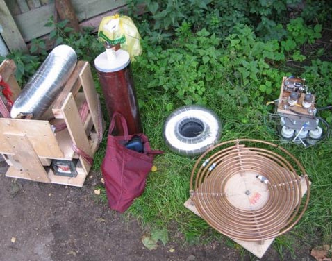
and further:
Finally, the turn came to the transformer Tesla : the primary winding consists of 7-9 turns of a very large cross-section wire, however, a copper plumbing pipe is suitable. The secondary winding contains from 400 to 800 turns, here it is necessary to adjust. The primary winding is fed. At the secondary, one pin is reliably grounded, the second is connected to the torus (lightning emitter). The torus can be made from a vented corrugation.
And further:
A small video about the self-made Tesla coil =)
As it is not surprising, however, this remarkable device still has no practical application. Some create attractions, other fixtures and tricks. One eccentric and did manage to create a Christmas tree. The colors he obtained were due to the deposition of various substances on the radiator. For example, if you apply a solution of some kind of boric acid, then the crown will be green. If manganese, it seems to be bright blue, if lithium, then crimson. So, Tesla's coil in the hands of modern man has become a toy and only.

Comments
When commenting on, remember that the content and tone of your message can hurt the feelings of real people, show respect and tolerance to your interlocutors even if you do not share their opinion, your behavior in the conditions of freedom of expression and anonymity provided by the Internet, changes Not only virtual, but also the real world. All comments are hidden from the index, spam is controlled.