Beacon for child protection from kidnapping
Beacon for protecting children from kidnapping
This device was tested in the laboratory of the magazine "Rad i oamator " . When tuning the circuit, not every radio amateur will have the devices listed in the diagram. If they are not available, the circuit can be adjusted using an oscilloscope with a bandwidth of up to 100 MHz, tester, power supply, two radios, the simplest indicator of the field strength. The correctly assembled circuit starts working immediately. The oscilloscope controls the operation mode of the low-frequency oscillators according to the diagrams in Fig. 3. Next, the HF cascade is tuned, controlling the operation of the transmitter by two radio receivers located at different distances from the transmitter, and an indicator of the field strength. It is better to place the receiver antenna on the windowsill.
A small-sized electronic device is intended for the timely submission of an alarm signal in the event of an attempted attack, kidnapping or robbery. This device is placed in the pocket and, if necessary, is switched to the "Alarm" mode. Children who play near the house, parents will be able to provide the necessary assistance. At home, there is a control radio tuned to the corresponding FM or VHF frequency, which gives an intermittent alarm signal resembling the sound of a police siren leaving to detain criminals.
While walking, the child switches the device switch to the "1" ( "Standby" ) position. In this mode, from the dynamics of the radio control receiver located in the apartment, rare (once in 30-60 C) quiet sounds - a signal that the device is in the on state. If necessary, the switch is moved to the "2" ( "Alarm" ) position, and intermittent signals are heard from the speaker, the LED flashes on the beacon.
The whole construction is located on the printed
Board for a specific building, which can acquire a radio amateur.
In Fig.
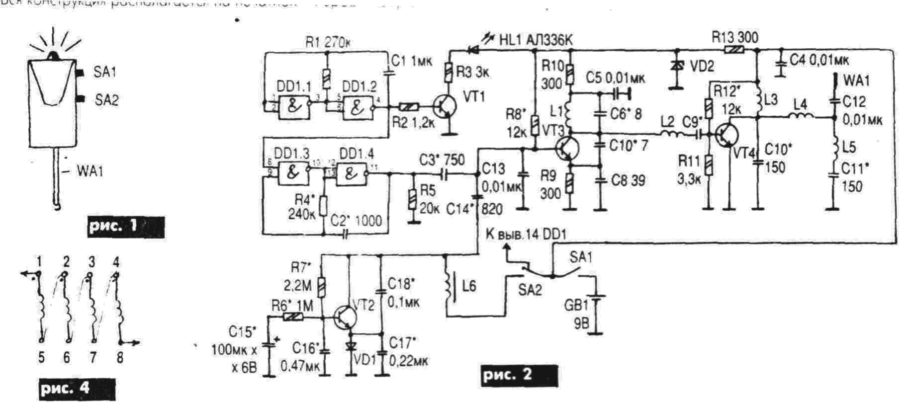
1 depicts one of the design options - the radio beacon in the marker, which has a clip for fastening, so it is convenient for them to use children.
At the top is LED HL 1, on the side - power switch SA 1, switch mode SA 2, at the bottom - antenna from steel wire length
The power source is a "Krona" battery, a 9 V battery or a miniature battery for powering the vehicle's on / off system.
The alarm operates in the FM band (88 ... 108
MHz) or VHF (66 ... 74
MHz), in the free space overlaps the distance of at least
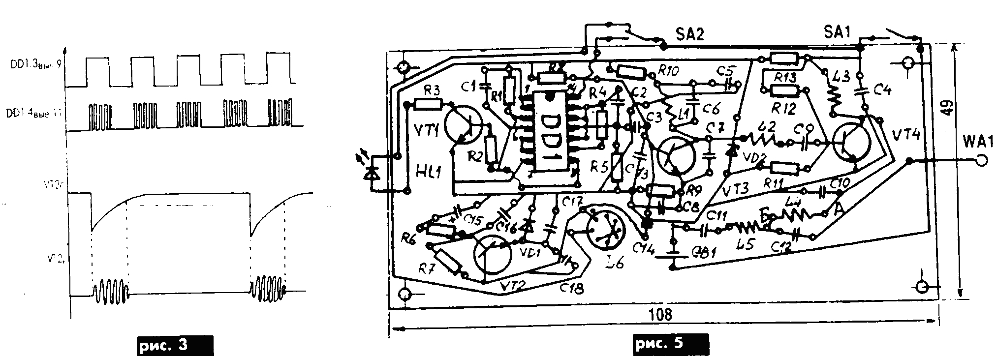
Schematic diagram of the device is shown in Fig. 2. Elements DD 1.1 and DD 1.2 generate a signal of frequency 1 Hz, which controls the operation of the generator on the elements DD 1.3 and DD 1 4, generating a frequency of about 2 KHz. At the output of the element DD1.2 switched on transistor VT 1 for light alarm in case of an alarm. To generate the "Standby mode" signal, a generator of intermittent audio frequency generation on the transistor VT 2 is assembled. The generation frequency is determined by the inductance of L 6 and the circuit capacitances. During the generator setup, the on and pause times can be varied within wide limits. In Fig. 3 shows the time diagrams of the generator.
On the transistor VT 4, a power amplifier is assembled, to which an antenna is connected via a Collins filter ( P-circuit ).
The details in the scheme are better to use miniature, imported production, having preliminarily checked their quality. All resistors of type ОМЛТ-0,125; Capacitors C 6 ... C 8 type KT, ST5 type K50-35, the rest type KM. Transistors VT 1 ... VT 3 type KT315B (KT315G, KT312B, KT342B), VT4-2T371A (KT367A, KT372B, KT382B), diode VD 1 type D9B (D2, D18, D310), LED HL1 type AL336K (AL307B, AL102B), Zener diode VD 2 type 2S156A, switches SA1, SA2 - PD9-2, DD1 chip type K561LA7 (564LA7). Throttle L6 unified - transformer pulse miniature ТИМ-170. The scheme of its connection is shown in Fig. 4. In case of its absence, wind the wire with PEV-1 wire Ø 0.1 mm on the ferrite ring M2000K 12x8x3. Contour coils are wound with a PEV-2 wire Ø 0.71 mm on a Ø 5 mm mandrel. The coils L 1 and L 2 have 5 turns, L 3 and L 5 - 7 turns, and L 4 - 4 turns.
For the installation (Fig. 5), a foiled Getinax is used.
The printed conductors of the RF generator should be tamped to eliminate their inductance and make it wider.
To install TIM-170 in the board, drill 8 holes Ø 0.5 mm.
When using a homemade choke, the winding should be wrapped with fluoroplastic insulation, the terminals should be made of wire and MGTF-
Configuring the schema. For this, the following devices are needed: an adjustable power supply unit with a power of at least 2 W, a tester, an oscilloscope with a bandwidth of up to 100 MHz, a GID, a wave meter, a field strength meter, a tube voltmeter, a control radio.
To check the node on the transistor VT 2 " Warning" it is necessary to solder the wire from the switch SA1, which is powered by the circuit of the high-frequency generator, and from the power supply supply 9 V. Switch the SA2 switch to position "1" . When configuring this node, you should keep in mind the following: the generator generates intermittent oscillations of the sinusoidal shape, the capacitors C16-C18 are in the feedback loop and serve to start the generator. Together with the coil L 6 they determine the tone of the sound in the radio control receiver. The selection of the ratings of these capacitors affects the operating mode of the generator. The capacitance of the capacitor C16 affects the frequency of the generator.
The duration of the generation is determined by the resistors R 6, R 7. Increasing the capacity of C16 increases the pause and saves battery power. Reducing the resistance of R6 and R7 increases the frequency of switching on the generator . To monitor the robots of this generator, connect the oscilloscope to the base of the transistor VT 3, and through a capacitor with a capacity of 510 PF - headphones. During normal operation of the generator, splashes of a sinusoid are visible on the screen, and a musical tone is heard in the headphones. In the absence of oscillations, C17, C18 should be selected or the inductance of coil L6 increased. The required timbre of sound is determined mainly by the value of the inductance: the higher it is, the lower the frequency of sound.
Then switch SA2 is moved to position "2" "Alarm" . The LED HL 1 starts flashing at once , on the oscilloscope screen, bursts of rectangular pulses are visible . Resistor R 1 regulates the pulse width and amplitude: the greater the resistance R1, the shorter the duration and vice versa, and R 4 and C 2 determine the frequency of the generator addition. When finalizing the radio beacon, you should select the capacitances C3 and C14 to eliminate overmodulation , and also so that the generator does not "stall" .
To test the RF generator on the VT3 transistor, the capacitors C3, C14 should be decoupled, and the power cable from the SA1 should be restored. To the collector VT3 through a capacitor with a capacity of 10 pF to connect the oscilloscope. Instead of R 8 and R 12, turn on potentiometers 100 kΩ with a 1 kΩ limiting resistor , and replace R 9 with a 3 kΩ potentiometer and put it at 300 Ω. By adjusting R8 to achieve generation of oscilloscope screen, sometimes a selection of C 7 is required. Adjusting R8 and R9, find the net and maximum amplitude of the voltage. Then reduce the supply voltage to 6 V and adjust R8, R9 to find the maximum voltage for this supply voltage, and then set the average value to 6 ... 9 V.
After that, connect the real antenna and check the operation of the power amplifier on the transistor VT 4. The circuit uses a microwave transistor, so even minor changes in capacitance C 9 affect the output power and operating frequency (with increasing capacity, the frequency decreases and the output power increases). For tuning, instead of C 9, solder the tuning capacitor by 1.9 / 20 pF, and connect the oscilloscope to the collector VT4. Instead of C10 and C11 solder capacitors with capacitance up to 150 pF. To adjust the C 9, you need a screwdriver made of plexiglas, textolite, etc. When the master oscillator is running, adjusting C 9 and R 12, achieve maximum voltage on the collector VT4. The collector current measured by the tester must not exceed 18 mA at 9 V supply. Adjusting С 9 , it is necessary to control the working frequency with the help of GIR and wave meter, so that it does not go beyond the operating range of the radio control receiver. In accordance with the current GOST on the range of 88 ... 108 MHz, radios operate above 100 MHz, hence, the beacon should be located below 100 MHz. On the domestic band, the radio beacon frequency should be above 70 MHz.
The next stage is the adjustment of the maximum output power of the cascade to VT4 and the adjustment of the P-filter , which allows to match the antenna length to the maximum output power, and also suppresses the harmonics.
The adjustment is carried out mainly by changing the capacitances C10 and C11 for a fixed value of the inductance L 4. To properly adjust the filter, the capacitors C3 and C14 must be soldered into the circuit and again check the voltage and curve shape on the VT4 manifold and, if necessary, adjust them.
The ultimate goal of the filter setting is to obtain the maximum output power, and the range of the radio beacon depends on this.
At point B there must be a maximum voltage.
It is necessary to connect an oscilloscope here.
Adjusting C10 and C11, achieve maximum voltage.
This is also controlled by a field strength meter located at a distance
After the adjustment, the elements to be replaced should be replaced by constants of a similar value and inserted into the housing together with the battery; The frequency will then move downward. If necessary, by squeezing or expanding the turns L 1, adjust the frequency. In this case, it is necessary to adjust L 3.
Then the operation of the beacon is checked in real conditions. The radio control receiver should be placed on the apartment window from the side of the street where the beacon user will be located, the radio antenna fully extend. Place the radio beacon in the jacket pocket, place the antenna down. Switch on SA1, SA2 in the "1" position . The assistant in the apartment finds the best position of the antenna, turning it in different directions, and also the place in the apartment where the signal sounds louder. Then check mode "2" . Changing the position of the radio beacon in relation to the radio receiver, you can make a full picture of the use: go to the limit distance, go around the corner of the building, etc.
The final stage is the conduct of mechanical tests.
Turn on the control radio, find the beacon signal.
When on, the radio beacon should be dropped from the height
Literature
1. Voitsehowski J. Remote control of models. - Moscow: Communications, 1977. - 432 p .

Comments
When commenting on, remember that the content and tone of your message can hurt the feelings of real people, show respect and tolerance to your interlocutors even if you do not share their opinion, your behavior in the conditions of freedom of expression and anonymity provided by the Internet, changes Not only virtual, but also the real world. All comments are hidden from the index, spam is controlled.