
|
Start of section
Production, amateur Radio amateurs Aircraft model, rocket-model Useful, entertaining |
Stealth Master
Electronics Physics Technologies Inventions |
Secrets of the cosmos
Secrets of the Earth Secrets of the Ocean Tricks Map of section |
  |
| Use of the site materials is allowed subject to the link (for websites - hyperlinks) | |||
Navigation: => |
Home / Electronics / Schemes / Power supply of equipment / |
|
SCHEMES OF DEVICES FOR REGENERATION OF GALVANIC
ELEMENTS OF FOOD (BATTERY)
Author of the article: Unknown
The problem of re-use of galvanic cells has long worried fans of electronics. In the technical literature, various methods of "revitalizing" the elements were repeatedly published, but, as a rule, they helped only once, and the expected capacity was not given.
As a result of the experiments, it was possible to determine the optimum current regimes of regeneration and to develop chargers suitable for most elements. At the same time, they acquired the original capacity, and sometimes somewhat superior to it.
You need to restore the elements, and not the batteries of them, because even one of the battery cells connected in series, which has become unusable (discharged below the permissible level) makes it impossible to restore the battery.
As for the charging process, it should be conducted with an asymmetric current of 2.4 ... 2.45 V. With a lower voltage regeneration is very prolonged and the elements after 8 ... 10 hours do not dial and half the capacity. With greater tension, cases of effervescence of elements are not uncommon, and they become worthless.
Before starting the charging of the element, it is necessary to carry out its diagnostics, the purpose of which is to determine the ability of the element to withstand a certain load. To do this, first connect a voltmeter to the element and measure the residual voltage, which should not be less than 1 V. (An element with a lower voltage is unsuitable for regeneration.) Then the element is loaded for 1 ... 2 seconds with a 10-ohm resistor , and if the cell voltage drops by no more than 0.2 V , it is suitable for regeneration.
The electrical diagram of the charger, shown in Fig. 1 (proposed by BI Bogomolov), is designed to charge six elements simultaneously ( G1 ... G6 of type 373, 316, 332, 343 and other similar ones).
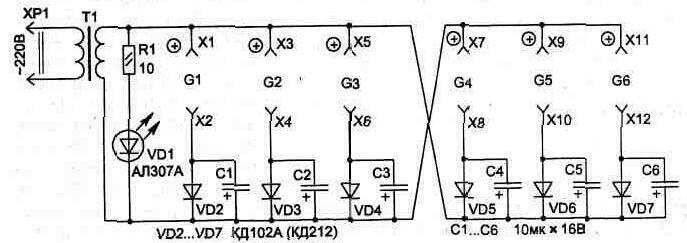
Fig. 1
The most important part of the circuit is the transformer T1 , since the voltage in the secondary winding must be strictly within 2.4 ... 2.45 V, regardless of the number of regenerated elements connected to it.
If a finished transformer with such an output voltage can not be found, it is possible to adapt an existing transformer with a power of at least 3 W , wound it with an additional secondary winding for the desired voltage with a PEL or PEV wire with a diameter of 0.8, 1.2 mm . The connecting wires between the transformer and the charging circuits must be as large as possible.
The duration of regeneration is 4 ... 5 , and sometimes 8 hours . Periodically, one or the other element must be removed from the unit and checked by the method given above for the diagnostics of the elements, and can be monitored using a voltmeter for voltage on the charged elements and, once it reaches 1.8 ... 1.9 V , regeneration To cease, otherwise the element can be recharged and fail. Similarly, if any element is heated.
The elements that work in children's toys are best restored if they are put on regeneration immediately after the discharge. And such elements, especially with zinc glasses, allow for multiple regeneration. The modern elements in the metal case behave somewhat worse.
In any case, the main thing for the regeneration is not to allow a deep discharge of the element and put it on time in a timely manner, so do not rush to throw out the spent galvanic cells.
The second circuit ( Figure 2 ) uses the same principle of charging elements with a pulsating asymmetrical electric current. It is offered by S. Glazov and is easier to manufacture, since it allows any transformer to be used with a winding having a voltage of 6.3 V. The incandescent lamp HL1 (6.3 V, 0.22 A) performs not only signal functions, but also limits the charging current of the element, and also protects the transformer in the event of short circuits in the charging circuit.
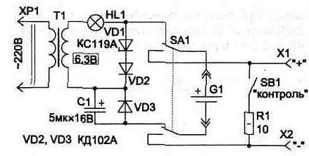
Fig. 2
Zener diode VD1 type KC119A limits the voltage element charge. It can be replaced by a set of diodes connected in series - two silicon and one germanium - with an allowable current of at least 100 mA . Diodes VD2 and VD3 - any silicon with the same permissible average current, for example KD102A, KD212A .
Capacitor C1 capacitance - from 3 to 5 μF for operating voltage not less than 16V . The circuit is from the switch SA1 and the control jacks X1, X2 to connect the voltmeter. Resistor R1 - 10 Ohm and button SB1 serve to diagnose the element G1 and control its state before and after regeneration.
The normal state corresponds to a voltage of at least 1.4 V and its reduction when the load is connected to no more than 0.2 V.
The degree of charge of the element can also be judged from the brightness of the illumination of the lamp HL1 . Before connecting the element, it glows about half a full length. When connecting a discharged cell, the luminescence brightness increases noticeably, and at the end of the charging cycle, connecting and turning off the element almost does not cause a change in brightness.
When recharging items such as SC-30, SC-21 and others (for wristwatches), it is necessary to include a 300 ... 500 Ohm resistor in series with the element. Elements of the battery type 336 and others are charged in turn. To access each of them, you need to open the cardboard bottom of the battery.
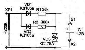
Fig. 3
If you only need to restore the charge to the batteries of the SC series, the regeneration circuit can be simplified by eliminating the transformer ( Figure 3 ).
The scheme works similarly to the above. Charging current ( I zer) of element G1 flows through elements VD1, R1 at the moment of positive half-wave of mains voltage. The value of I depends on the value of R1 . At the moment of a negative half-wave, the diode VD1 is closed and the discharge goes along the circuit VD2 , R2 . The ratio I zar and I times is chosen to be 10: 1 . Each type of element of the SC series has its own capacity, but it is known that the value of the charging current should be about a tenth of the electric capacity of the battery. For example, for SC-21 , a capacitance of 38 mAh (Iasar = 3.8 mA, Ipac = 0.38 mA) , for SC-59 - a capacitance of 30 mAh (Iasar = 3 mA, Iasp = 0.3 mA ) . The diagram shows the resistor values for the regeneration of the elements of SC-59 and SC-21 , and for other types it is easy to determine using the relations: R1 = 220/2 · lsap, R2 = 0,1 · R1 .
The zener diode VD3 installed in the charger does not participate in the operation of the charging device, but it acts as a protective device against electric shock - when the element G1 is disconnected at terminals X2 and X3, the voltage can not increase more than the stabilization level. Stabilitron KS175 is suitable with any last letter in the designation or it can be replaced by two Zener diodes type D814A , included in series to meet each other ("plus" to "plus"). As diodes VD1, VD2 any with a working return voltage of at least 400 V is suitable.
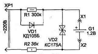
Fig. 4
The regeneration time of the elements is 6 ... 10 hours . Immediately after the regeneration, the voltage on the element will slightly exceed the passport value, but after a few hours the rated voltage will be 1.5 V.
In this way, SC elements can be restored three to four times if they are put on time to recharge, not allowing a full discharge ( below 1V ).
The similar scheme is shown in Fig. 4 . She does not need special explanations.
print version
Author unknown
PS The material is protected.
![]()

Comments
When commenting on, remember that the content and tone of your message can hurt the feelings of real people, show respect and tolerance to your interlocutors even if you do not share their opinion, your behavior in the conditions of freedom of expression and anonymity provided by the Internet, changes Not only virtual, but also the real world. All comments are hidden from the index, spam is controlled.