
| Start of section
Production, amateur Radio amateurs Aircraft model, rocket-model Useful, entertaining |
Stealth Master
Electronics Physics Technologies Inventions |
Secrets of the cosmos
Secrets of the Earth Secrets of the Ocean Tricks Map of section |
  |
| Use of the site materials is allowed subject to the link (for websites - hyperlinks) | |||
Navigation: => |
Home / Electronics / Schemes / Power supply of equipment / |
|
SCHEME OF PULSE TRANSDUCER WITH 12 V IN 220 V 50 Hz
Sometimes, in the absence of network wiring, there is a need to feed household electrical appliances from the vehicle's on-board network. The literature describes a lot of the simplest converters from 12 to 220 V , but working at a higher frequency. For a lighting lamp or an electronic fishing rod, this is still acceptable, but not all household appliances designed for a frequency of 50 Hz can operate at a higher frequency. In addition, none of the published schemes have protection against overload.
Any home appliances up to 100 W can be connected to this converter (using a more powerful transformer it can be increased).
The proposed circuit of the converter ( Fig. 1 ) operates at a frequency of 50Hz and has protection against overcurrent. In addition, this converter gives the output signal form, more approximate to the sine, which reduces the level of high-frequency harmonics (interference).
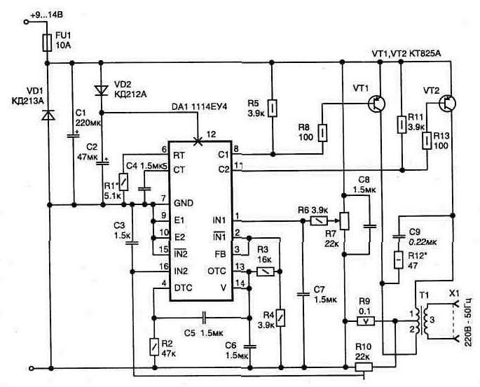
Fig. 1 Schematic diagram of a pulse converter from 12 V to 220 V 50 Hz
The device is assembled on a chip specially designed for switching power supplies 1114ЕУ4 (import analogue TL494CN or TL494LN ). This makes it possible to reduce the number of applied parts and make the circuit fairly simple.
Inside the chip there is an autogenerator with a circuit for obtaining output pulses with pulse-width modulation, and a number of additional nodes providing its extended capabilities. The work of the microchip is described in detail in the reference literature [ L17 ].
The output keys of the chip are designed for a current of no more than 200 mA , and to control the higher power, the output pulses are fed to the base of the key transistors VT1, VT2 . The VD1 diode prevents damage to the circuit when the polarity of the power connection is incorrect (only the input fuse FU1 will burn out).
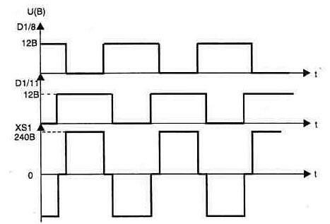
Fig. 2 Form of voltage in control points
The adjustment of the device begins when the transformer is disconnected from the setting frequency of the master oscillator of 100 Hz using the time-setting circuit from the resistor R1 and capacitor C4 . Since the chip has a push-pull output, the output frequency is half the oscillator frequency ( 50 Hz on the outputs DA1 / 8 and DA1 / 11 ). Resistor R7 adjust the shape of the output pulses of the chip in accordance with the diagram shown in Fig. 2 . After that, we connect the transformer, and at the supply voltage of the circuit from the 12- volt source, the resistor R7 sets the rated voltage in the secondary circuit 220 V (measured with a dial gauge). This is done with a connected load of 25 ... 60 W.
A circuit made of a resistor R12 and a capacitor C9 may require a selection of values in order to remove the outliers in the transformer from the edges at the moment of transients when the current is switched.
The current protection of 10 A is set by the resistor R10 . This prevents damage to the converter in the event of an overload or short circuit on the output, since the circuit begins to lower the output voltage by switching to the current stabilization mode.
The converter has no feedback on the output voltage, since the practical experience shows that it changes insignificantly when the power of the connected load changes and does not exceed the permissible range of 190 ... 240 V.
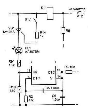
Fig. 3 Protection circuit of the impulse converter
The converter consumes no more than 1 A at idle speed, and with the load, the current increases in proportion to the power.
Transistors are installed on a radiator with a surface area of at least 300 square meters. See
Transformer T1 will have to be manufactured independently. A magnetic circuit of the type PLM27x40-73 or similar was used. Windings 1 and 2 contain 14 turns of PEL-2 wire 2 mm in diameter ; Winding 3 contains 700 turns of wire diameter 0.5 mm . Windings 1 and 2 must be symmetrical - this condition is easily met when they are simultaneously wound (two wires at once).
The circuit uses the following parts: capacitors C1, C2 of type K52-1 , C3 ... C8 - type K10-17 , C9 - K73-17V ; Constant resistors R9 type C5-16MV , R12 - C5-5 . And other types of MLT ; Tuning R7 type C5-2 .
A 10 A fuse can be made from a copper wire 0.25 mm in diameter .
If the inverter is overloaded, when the current limiting mode is activated, the reduced supply voltage is not permissible for all radio electronic devices. In this case, the current protection can be performed with an automatic full tripping of the converter, Fig. 3 . For these purposes, it is convenient to use the current relay K1 , whose contact group includes a thyristor VS1 . Such a relay is easy to manufacture independently on the basis of a reed switch, and a variant of the K1 design is shown in Fig. 3 . The current at which the contacts of the reed switch K1.1 are closed is adjusted by changing the number of turns of the winding (one layer is enough).
When the protection is activated, the HL1 indicator lights up, and in order to return the circuit to the operating state, it is necessary to disconnect the inverter power for a while.
print version
Date of publication 25.12.2003gg
![]()

Comments
Commenting on, remember that the content and tone of your message can hurt the feelings of real people, show respect and tolerance to your interlocutors even if you do not share their opinion, your behavior in the conditions of freedom of expression and anonymity provided by the Internet, changes Not only virtual, but also the real world. All comments are hidden from the index, spam is controlled.