| Start of section
Production, amateur Radio amateurs Aircraft model, rocket-model Useful, entertaining |
Stealth Master
Electronics Physics Technologies Inventions |
Secrets of the cosmos
Secrets of the Earth Secrets of the Ocean Tricks Map of section |
  |
| Use of the site materials is allowed subject to the link (for websites - hyperlinks) | |||
Navigation: => |
Home / Patent catalog / Catalog section / Back / |
|
INVENTION
Patent of the Russian Federation RU2120170
![]()
VS GRIGORCHUK'S SINGLE-CONDUCTING SYSTEM FOR TRANSFER OF ELECTRIC POWER
The name of the inventor: Grigorchuk Vladimir Stepanovich
The name of the patent holder: Grigorchuk Vladimir Stepanovich
Address for correspondence:
Date of commencement of the patent: 1997.01.28
The invention is intended for direct current transmission. The single-wire power transmission system comprises a transmitting substation with a generator and a step-up transformer receiving a substation consisting of a receiver and a negative-potential generating device, both of which are connected by a high-voltage line. Moreover, the transmitting substation contains an additional rectifier and a capacitor bank, and the receiving substation in the receiver has a high-voltage receiving capacitor. The input of the high-voltage direct current converter to the alternating three-phase current is connected by the windings of the step-down transformer. The negative potential generating unit of the receiving substation has a direct current source, a DC to AC converter, and a rectifying device connected to the capacitor bank, the negative terminal of which is connected to the negative terminal of the high-voltage receiving capacitor, the charger. One end of the high-voltage line is connected to the positive terminal of the capacitor bank of the transmitting station, and the other end to the positive terminal of the high-voltage receiving capacitor of the receiving substation. The transmitting substation forms positive charges of electricity and transfers them to a receiving substation that converts the received positive charges of electricity into alternating three-phase current of standard frequency and supplies it to consumers. The technical result consists in reduction of electric and thermal losses and increase of operational qualities.
DESCRIPTION OF THE INVENTION
The invention relates to the field of electrical engineering and can find application in power transmission systems.
A two-wire electric power transmission system containing a constant current source, a switch, an electric power consumer and connecting wires is known. IA Mamzelev, GG Kapelin, Fundamentals of Radioelectronics, Moscow: Prosveshchenie, 1978, p. 17, Fig. 9/.
The disadvantages of the known two-wire power transmission system are a small transmitted power, electrical losses in the conductors, a low source voltage and a small transmission distance of electricity.
These shortcomings are determined by the resistance of the electrical circuit and the design of the system.
A high voltage direct current transmission system is also known, comprising a transmitting station with a generator raising and rectifying devices, receiving a substation with a receiving and lowering device, a high-voltage line connecting the transmitting and receiving substations / Overview: "Energy and Electrification", series 4 " Electrical networks and systems ", Issue 5" Working Grounds for DC Power Transmission ".- M., Center for Scientific and Technical Information on Energy and Electrification, 1987, p. 2, Fig. La).
The known system of high-voltage direct current electric power transmission, which is the closest in terms of technical essence and achieved useful result, is accepted as a prototype.
The disadvantages of the known high-voltage direct current transmission system adopted for the prototype are: electrical and thermal losses in the high-voltage line, increased danger to the environment, and a high consumption of non-ferrous metals.
These shortcomings are due to the high transfer voltage, the resistance of the high-voltage line and the selected power transmission system.
The purpose of the present invention is to reduce electrical and heat losses and improve the performance of the power transmission system.
Said goal in accordance with the invention is ensured by the fact that a two-wire high-voltage line, a high-voltage DC-to-AC converter and a step-down single-phase transformer of a receiving substation are replaced by a capacitor bank mounted on a transmitting substation and electrically connected to the output of a high voltage rectifier device, a high-voltage receiving capacitor, A three-phase alternating current converter whose input is connected to a high-voltage receiving capacitor, a three-phase step-down transformer whose primary windings are electrically connected to the output of a high-voltage DC-to-AC converter to an alternating three-phase current, and the secondary windings are connected to the consumers, a negative potential generating device comprising a source A charger connected to one of the secondary windings of a three-phase transformer, a DC to AC converter, a boosting and rectifying device, a battery of capacitors whose negative terminal is connected to the negative terminal of a high-voltage receiving capacitor, a single-wire high-voltage line mounted on insulators attached to Metallic posts and connecting the positive terminal of the capacitor bank of the transmitting substation with the positive terminal of the high-voltage receiving capacitor of the receiving substation.
The essence of the invention is explained in the drawings, where
 |
 |
FIG. 1 shows a general view of a single-wire power transmission system; In Fig. 2 is a block diagram of a single-wire power transmission system.
 |
 |
 |
FIG. 3 - diagram of connection of several receiving substations to a single-wire high-voltage line; In Fig. 4 - general view of the receiving capacitor; In Fig. 5 - receiving condenser device.
 |
 |
 |
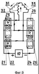 |
FIG. 6 - the device of a high-voltage DC-to-AC converter in three-phase alternating current; In Fig. 7, 8, 9 - scheme of operation of a high-voltage DC-to-three-phase alternating current converter.
FIG. 10 is an electrical diagram of a single-wire power transmission system.
A single-wire power transmission system comprises a building of a power plant 1 in which a steam turbine is located with all auxiliary mechanisms (not shown) driving a single-phase alternator 2. The transmitting substation 3 comprises a step-up transformer 4 whose primary winding is connected to a generator, rectifying A device 5 made on semiconductors whose input is connected to the secondary winding of the step-up transformer, and the output is connected to a battery of capacitors 6 which are connected together in parallel.
The receiving substation 7 consists of a receiver 8 and a negative potential generating device 9. The receiving device comprises a high voltage receiving capacitor 10, a high voltage DC to three-phase alternating current high voltage 11, a step-down transformer of a three-phase alternating current 12. The high-voltage receive capacitor comprises a housing 13 closed Lid 14, on which positive terminals 16 and negative terminals 17 are mounted on insulators 15. A glass vessel 18 is placed inside the casing, in the walls of which there is soldered a pack of positive plates 19 connected by a conductor and connected to positive terminals of the casing. A pack of negative plates 20 is inserted with a clearance inside the stack of positive plates, which are soldered into the walls of the glass vessel, connected together by a conductor and connected to the negative terminals of the housing. The space between the plates is filled with hydrogen under a pressure of 40-50 kPa. The high-voltage DC to three-phase alternating current converter includes input diode optocouplers 21, 22, 23 and output diode optocouplers 24, 25, 26. On the insulating plate 27, a movable contact 28 mechanically coupled to an electric motor (not shown) fed from Battery and interacting with nine fixed contacts 29 divided into three separate groups and by means of conductors connected to a low voltage electrical circuit with input and output optocouplers LEDs, a movable contact and a battery 30. The high voltage circuit includes primary windings 31, 32, 33 lowering Three-phase transformer and photodiodes of input and output optocouplers, connected with each other by conductors and connected to the terminals of a high-voltage receiving capacitor. The secondary windings 34, 35, 36 of the step-down three-phase transformer are connected to the consumer 37. The negative potential generating device includes a battery 38 with a charging device 39, a reverse current relay 40, a DC to AC converter 41, a boost device 42 and a capacitor bank 43. Charger The device comprises a switch 44, a variable resistor 45, a rectifier diode 46, an indicator light 47 connected in series with a load resistor 48 connected in series with one of the secondary windings of the step-down three-phase transformer. The charger is connected via a movable and fixed relay contacts to a battery having a switch 49. The battery load is a DC to AC converter connected in series with the relay winding and is a sinusoidal pulse generator made on two transistors with a transformer output connected To the input of the step-up device, which is a cascade generator with sequential power to the capacitors, the output of which is connected to a capacitor bank, the negative terminal of which is connected by a conductor to the negative terminal of the high-voltage receiving capacitor. The transmitting and receiving substations are interconnected by a single-wire high-voltage line. It contains high-voltage supports 50, on which, on the insulators 51, a wire 52 is tensioned, one end of which is connected to the positive terminal of the capacitor bank of the transmitting substation, and the other is connected to the positive terminal of the high-voltage receiving capacitor of the receiving substation.
WORK OF A SINGLE-CONDUCTIVE SYSTEM FOR TRANSFER OF ELECTRICITY
The principle of the operation of a single-wire transmission system is the formation of positive electricity charges by the transmitting substation and transferring them along the line to the receiving substation, which converts the received positive charges into three-phase alternating current of the standard frequency and supplies it to consumers.
A steam turbine (not shown) installed in the building of the power plant 1 drives a generator 2 which generates a single-phase alternating current supplied to the primary winding of the step-up transformer 4 of the transmitting station 3. The alternating magnetic field crosses the turns of the secondary winding of the step-up transformer and creates a current therein High voltage, which is supplied to the input of the rectifying device 5, where a single-phase alternating current is converted into a pulsating current of constant direction. The resulting high-voltage current is supplied to charge the capacitor bank 6. Next, positive charges from the capacitor battery plates drain onto the high-voltage line wire 52, are evenly distributed over its entire length and then enter the input terminals 16 and plates 19 of the high-voltage receiving capacitor 10 of the receiving substation 7. Closing the electrical circuit with the switch 49, the direct current from the battery 38 will be fed to the input of the converter 41 where it is converted to an alternating current which is input to the input of the boosting device 42 where it is raised and rectified, after which it is supplied to a battery of capacitors 43. C Capacitor banks, negative charges through the conductor are applied to the negative terminals 17 and to the plates 20 of the high-voltage receiving capacitor 10. When anode plates 19 are accumulated, positive charges of electricity near them cause avalanche ionization of hydrogen atoms. The positive ions formed in this case move under the action of the electric field created by the negative potential towards the negative plates 20 of the high-voltage receiving capacitor 10, which in this case are cathodes. Under the impact of hydrogen ions from the surfaces of the plates 20 / cathodes / electrons are knocked out, which rush towards the positive plates 19 / anodes /, creating new ions in their path. As a result, electron-ion emission arises and an electric current flows between the positive plates 19 and the negative plates 20, the magnitude of which will be determined by the degree of ionization and the magnitude of the positive charge coming from the transmitting station 3. In the discharge space between the plates 19 and 20, along with the ionization process, And the reverse process is the recombination of electrons and ions, as a result of which neutral atoms are newly formed. In this case, an electron plasma arises between the plates 19 and 20 and a dynamic equilibrium sets in: the number appearing due to ionization of the charge carriers is equal to the number of carriers disappearing during the same time as a result of recombination. Owing to the high concentration of electrons and ions, the plasma will have a high conductivity and its potential will be equal to the potential of positively charged plates. 19 / On the processes taking place in gas-discharge devices see Batushev VA, Electronic devices. - Moscow: Higher School, 1980, p. 297-323). The high-voltage direct current arising on the plates 19 and 20 of the high-voltage receiving capacitor 10 is removed and fed to the input of a high-voltage converter 11, which converts it into a three-phase alternating high-voltage current in the following manner. When the motor (not shown) is rotated, it rotates with the corresponding speed in the direction indicated by the arrow in Fig. 6, a movable contact 28 which alternately closes the fixed contacts 29. When the upper fixed contacts 29 close, the current from the battery 30 passes through the LEDs of the input diode optocouplers 21, 22 and through the LED of the output diode coupler 26. As a result, the conductivity of the photodiodes of the indicated diode optocouplers , Which was zero, increases to the maximum value. The high-voltage DC current taken from the high-voltage receiving capacitor 10 will pass through the photodiodes of the diode optocouplers 21, 22, the primary windings 31, 33, 32 of the step-down three-phase transformer 12, the output photodiode of the diode coupler 26 in the direction indicated by the arrows in FIG. 7. Further, rotating, the movable contact 28 closes the right lower stationary contacts 29. The current from the battery 30 passes through the LEDs of the diode optocouplers 22, 23, 24, which increase the conductivity of the corresponding photodiodes to the maximum value. The high-voltage DC current from the high-voltage receiving capacitor 10 flows through the photodiodes of the optocouplers 22 and 23, the primary windings 31, 32, 33 of the step-down three-phase transformer 12 and then through the photodiode of the diode coupler 24, as shown in FIG. When the left lower fixed contacts 29 are closed by the movable contact 28, the current from the battery 30 flows through the LEDs of the diode optocouplers 21, 23, 25, which, by illuminating the photodiodes of these diode optocouplers, increase their conductivity to the maximum value and the high current direct current from the high-voltage receiving capacitor 10 Passes through the photodiodes of the diode optocouplers 21, 23, the primary windings 32, 33, 31 of the step-down three-phase transformer 12 and the photodiode of the diode optron 25, as shown in FIG. 9. Thus, the movable contact 28, successively closing the fixed contacts 29, The voltage passing through the primary windings 31, 32, 33 of the step-down three-phase transformer 12 and creating an alternating magnetic field that crosses the turns of the secondary windings 34, 35, 36 of said transformer, inducing a three-phase alternating low voltage current that is supplied to consumers 37. At this time Operation of the receiving substation 7, the battery 38 of the negative potential generating device 9 is discharged and it needs to be recharged. For this, by closing the switch 44, the input of the charger 39 is connected to the load resistor 48. The parameters to be removed from the load resistor 48 by the alternating resistor 45 are determined. By means of the diode 46, it is rectified and fed through the movable and fixed contacts of the relay 40 to the battery 38. If the current drawn from the battery is large, then, passing through the winding of the relay 40, creates a strong magnetic field around it. The relay arm, overcoming the spring resistance, is attracted to the core, the movable and fixed contacts are opened and the battery charger 39 is disconnected from the battery 38. If the battery 38 is discharged, the current flowing through the winding of the relay 40 becomes insufficient to overcome the resistance of the spring , The movable and fixed contact relays 40 are closed and the battery 38 is connected to the charging device 39. Several transmitting substations 3 and several receiving substations 7 can be easily combined into a single power system (FIG. 3 /.
The positive effect of the invention: saving fuel and non-ferrous metals, increased safety of the high-voltage line, absence of electrical and thermal losses in the high-voltage line.
CLAIM
A single-wire power transmission system comprising a transmitting substation with a generator and a rectifying device whose input is connected to a secondary winding of the step-up transformer, a receiving substation with a receiving device and a step-down transformer whose secondary windings are electrically connected to the consumer, a high-voltage line, characterized in that The output of the rectifying device of the transmitting substation is connected to the capacitor bank and the receiver of the receiving substation comprises a high-voltage receiving capacitor connected to the input of the high-voltage DC-to-AC converter into an alternating three-phase current whose output is connected to the primary windings of the step-down transformer and electrically connected to the negative potential generating device, Comprising a DC source having a charger connected to one of the secondary windings of the step-down transformer and to the input of the DC to AC converter, whose output through the boosting current and the rectifying device is connected to a capacitor bank whose negative terminal is connected to the negative terminal of the high-voltage receiving capacitor of the receiving Devices of the receiving substation, the high-voltage line wire connecting the positive terminal of the capacitor bank of the transmitting substation with the positive terminal of the high-voltage receiving capacitor of the receiving substation.
2. A system according to claim 1, characterized in that the high-voltage receiving capacitor comprises a housing closed by a lid having positive and negative terminals mounted on insulators, inside of which is placed a glass or ceramic vessel filled with hydrogen under pressure, having inside the packages of positive and negative Plates inserted one into the other with gaps between them, the plates of one polarity being connected to each other and connected to the corresponding terminal of the housing, plates of opposite polarity and connected to each other and connected to another terminal of the housing.
3. The system according to claims. 1 and 2, characterized in that it comprises high-voltage metal supports arranged at a distance from each other on which insulators with a high-voltage line attached to them are fixed.
print version
Published on February 18, 2007
![]()

Comments
When commenting on, remember that the content and tone of your message can hurt the feelings of real people, show respect and tolerance to your interlocutors even if you do not share their opinion, your behavior in the conditions of freedom of expression and anonymity provided by the Internet, changes Not only virtual, but also the real world. All comments are hidden from the index, spam is controlled.