| Start of section
Production, amateur Radio amateurs Aircraft model, rocket-model Useful, entertaining |
Stealth Master
Electronics Physics Technologies Inventions |
Secrets of the cosmos
Secrets of the Earth Secrets of the Ocean Tricks Map of section |
  |
| Use of the site materials is allowed subject to the link (for websites - hyperlinks) | |||
Navigation: => |
Home / Patent catalog / Catalog section / Back / |
|
INVENTION
Patent of the Russian Federation RU2118698
![]()
POWER HYDROVACUUM INSTALLATION
The name of the inventor: Zarubin Stanislav Viktorovich
The name of the patent holder: Zarubin Stanislav Viktorovich
Address for correspondence:
The effective date of the patent: 1995.11.09
The installation is designed to produce electrical, thermal and other useful energy. The installation comprises a pressure device made in the form of a column, a guide for lifting the working fluid with the output nozzle accelerator in front of the accelerating stage of the impeller of the turbine. The turbine is located in a housing connected to a vacuum unit, made in the form of a two-way piston pump driven by a cylinder with compressed gas. At the same time, the turbine is connected to an actuator, for example an electric generator, by means of a step-up reducer and a flywheel. Such an installation makes it possible to obtain a useful form of energy in an environmentally friendly way.
DESCRIPTION OF THE INVENTION
The invention relates to power engineering and the production of turbines and can be used for environmentally friendly energy conversion, for example, into electrical, thermal or other useful form.
Turbines of hydroelectric power stations operating from the influence of falling masses of the water flow are known. The speed of water movement is the initial indicator for determining the capacity of hydroelectric power plants.
The spent water masses in the hydroturbines are discharged into the reservoir behind the dam (see The Great Soviet Encyclopedia, 1971, vol. 6, p.510).
Such hydropower plants are a complex complex of expensive facilities and equipment, they damage the environment, as they require land flooding.
The closest analogue of the invention is a vacuum hydroelectric power plant comprising a pressure device with a guide for lifting the working fluid (water), a housing connected to a vacuum unit, a turbine impeller connected to an actuator, for example an electric generator, and an auxiliary ballast and control equipment See RF patent No. 2005199 C1, cl. F 03 B 13/06, 1993).
However, this vacuum hydroelectric power plant requires the presence of a reservoir and does not ensure the ecological purity of the energy conversion process, since the working body (water) participates in an open technological process.
The object of the invention is to reduce the environmental damage and the cost of energy for domestic and industrial needs.
This technical and economic result is achieved due to the fact that the hydraulic power vacuum unit includes a pressure device with a guide for lifting the working fluid, a housing connected to a vacuum unit, a turbine impeller connected to an actuator, for example an electric generator, and an auxiliary ballast and control equipment, The turbine impeller is equipped with an accelerating stage and the guide is equipped with an accelerator nozzle, the vacuum unit being designed as a two-way piston pump driven by a compressed gas cylinder, the pressure device in the form of a column, and an actuator (electric generator) connected to the impeller Turbine by means of a reducer and a flywheel.
 |
 |
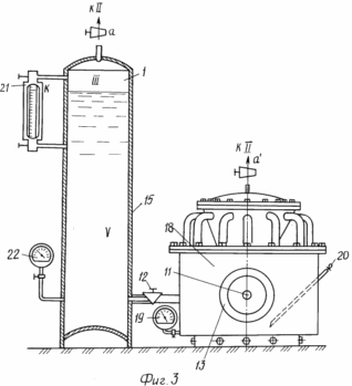 |
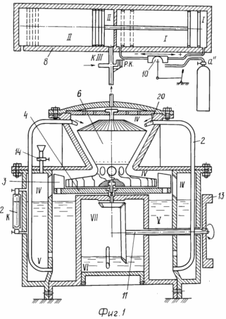
In Fig. 1 is a sectional view of the installation body and the vacuum unit with auxiliary control gear and control equipment; In Fig. 2 is a top view of the body and the turbine; In Fig. 3 - a general view of the body with a pressure column. The power vacuum unit contains: |
- emergency (control) valve 9 - FIG. 1 "RK" - manual or remote control;
- control panel 10 - pneumatic shower; Valve mechanism with camshaft; System of cranes, units can be either manual or remote control;
- working shaft 11 reducer;
- valve 12 regulator level of the working acceleration mass, can be manual or remote control;
- a flywheel 13 of conventional designation, can be used for mounting the clutch with an aggregate actuator (electric generator, gearbox, gearbox for power take-off shafts);
- filler receiver 14 - neck with three-way valve of manual or remote control;
- pressure column 15 - the volume and height of the level of the working fluid must exceed the volume and its level in the body;
- the control unit 16 - in FIG. 1,2,3 is not shown;
- a gear-box 17 of power shafts - in FIG. 1,2,3 is not shown;
- housing 18 - design and construction can be changed without disrupting the concept and direct designation;
- pressure gauge 19 - device for analytical control of the level of the working fluid in the housing case 18;
- channel 20 for communicating with the atmosphere of the crankcase of the reducer (nozzle) and monitoring the level of lubrication in it (feeler);
- water-measuring glass 21,21a with two three-way valves for visual control of working medium levels;
- manometer 22 - device for analytical control of the level of the working fluid in the pressure column 15.
I - high pressure zone.
II - control area.
III, IV - zones of working rarefaction.
V - pressure zone of the working fluid.
VI - the lubrication zone of the reducer.
VII - zone of atmospheric pressure.
A, a ', a' '- control valves.
K - control level of the working fluid.
The power vacuum installation works as follows.
Pre-prepare to start in the following sequence:
1. By opening the crane "a" air from the cylinder is fed to the air dam 10. The cranes "a" and "a" are set to the open position. Safety valve "R.K." Opened.
2. The filling of the internal cavities of the casing 18 and the pressure head (valve 12 is opened) through the filling receptacle 14 is performed by the solution of the working substance 1 to the mark K on the water glass 21a.
3. With the crane open, the devices 14 are closed with "RK" And control tap "a". By turning the handle of the control panel 10 the compressed air is supplied to the zone I of the vacuum unit 8. Moving to the left, the piston in the zone II creates a vacuum in the zone III of the pressure column 15, which raises the level of the working body 1 to the mark "K" on the water glass 21. The valve 12 And the tap "a" are closed.
4. The device 14 is used to top up the working fluid 1 in the housing 18 to the "K" mark on the water glass 21a with the open "RK" And "a" after the pistons of the vacuum unit 8 return to their home position using the control panel 10.
5. The tap of the filler receiver 14 and the "RK" is closed. With the help of the control panel 10, a vacuum is created in the zone IV of the housing 18. At the start of rotation of the flywheel 13, a valve "a" opens on the column 15 to balance the vacuum in it and the housing 18 and simultaneously opens the valve 12. By controlling the air supply by the control panel 10, In column 15 and casing 18 (communicating vessels) is brought to the design value, after which the valves "a" and "a" are closed, the installation is in operation.
The working body 1 on the rail 2 rises upwards, increases its speed in the nozzle-accelerator 2a. It is advisable to guide the guides 2 somewhat and arrange them evenly along the circumference of the housing 18.
After exposure to the working booster turbine (stage 6), the working body 1, under the influence of its own weight, falls on the accelerating blades 5 and then onto the blades 3 of the impeller 4, which does not have a rigid connection with the accelerating stage 6 but is rigidly connected through the drive gear with the working shaft 11, which increases the speed of the reducer, which rotates the flywheel 13, transmitting force to the actuator, for example an electric generator (not shown) that generates electric power for consumers. The working body 1, which has worked on the blades of the impeller, is returned to the housing crankcase 18 for further use in a closed working cycle.
The installation can be used on floating facilities and permanently with the removal of the working fluid from an open reservoir, which will be more effective at the seaside.
CLAIM
A power vacuum installation comprising a pressure device with a guide for lifting the working fluid, a housing connected to the vacuum unit, a turbine impeller connected to an actuator, for example an electric generator, and an auxiliary control gear and control equipment, characterized in that the impeller of the turbine is provided with an accelerating stage , And the guide - accelerator nozzle, with the pressure device in the form of a column, and the actuator is connected to the impeller of the turbine by means of a reducer.
print version
Date of publication 10.04.2007gg
![]()

Comments
When commenting on, remember that the content and tone of your message can hurt the feelings of real people, show respect and tolerance to your interlocutors even if you do not share their opinion, your behavior in the conditions of freedom of expression and anonymity provided by the Internet, changes Not only virtual, but also the real world. All comments are hidden from the index, spam is controlled.