
| Start of section
Production, amateur Radio amateurs Aircraft model, rocket-model Useful, entertaining |
Stealth Master
Electronics Physics Technologies Inventions |
Secrets of the cosmos
Secrets of the Earth Secrets of the Ocean Tricks Map of section |
  |
| Use of the site materials is allowed subject to the link (for websites - hyperlinks) | |||
Navigation: => |
Home / Patent catalog / Catalog section / Back / |
|
INVENTION
Patent of the Russian Federation RU2136515
![]()
METHOD OF POWER SUPPLY EQUIPMENT
AND DEVICE FOR ITS IMPLEMENTATION
The name of the inventor: Strebkov DS; Avramenko SV; Nekrasov A.I.
The name of the patent holder: All-Russian Scientific Research Institute of Agriculture Electrification
Address for correspondence: 109456, Moscow, 1-st Veshnyakovskiy pr., 2, VIESKH, Patent Department
The effective date of the patent: 1998.02.26
The invention relates to the field of power supply for vehicles and is intended for use in the sale of electric power for electric vehicles, electric forklifts, trams, trolleybuses and other vehicles with electric traction and rubber wheels. Electric energy is supplied to a monopolar electrostatic generator of electrical charges, and the charges received in the generator are moved through a contact single-wire network and current collectors to each electric vehicle and reverse the energy conversion of the electric field of the free charges to the electric energy of the alternating current. In the power supply device of electric vehicles between the high-frequency converter and the contact network, a monopolar electrostatic generator of electric charges is installed. This technical solution predetermines the high operational reliability of power supply and low power losses, and allows to obtain increased maneuverability of the electric vehicle with multi-row traffic.
DESCRIPTION OF THE INVENTION
The invention relates to methods of electrically powered electric transport and can be used to power trolleybuses, electric vehicles, electric forklifts, trams, electric tractors, electric locomotives and other electric vehicles.
There is a known method for feeding a rail electric vehicle, for example, a tram and an electric train, providing for the transmission of electrical energy through a single-wire contact network through a current collector to vehicles, converting the electric energy of the network to specified values and feeding it to traction motors (USSR, N 1729843, MKI 6 B 60 L 9/08, 1992 BI No. 16). A disadvantage of this method of electrically supplying a rail vehicle is the large metal capacity of the device necessary for the implementation of the method consisting of a two-wire conductive line containing a contact wire and a metal rail.
Another disadvantage is the inability to use this method for feeding non-rail electric transport, for example an electric vehicle or a trolleybus.
A method is known for supplying an electric vehicle by supplying electric power through a two-wire contact network, rod trolley current collectors to traction motors (USSR USSR N 1440767 MCI 6 B 60 L 5/34, BI N 441,1988).
The disadvantage of this method is a large consumption of conductor material. Another disadvantage is the low reliability of the trolley current collector, especially when driving at high speed and changing the direction and range of motion.
The method of supplying electrical devices and the device for its implementation using an alternating voltage generator by supplying the generator voltage to the low-voltage winding of the high-frequency transformer converter is the closest in technical essence to the invention. One of the input terminals of the power supply device is connected to one of the high voltage winding terminals of the high-frequency transformer converter, and a change in the generator frequency is achieved by establishing resonance oscillations in the formed electric circuit. The mode of resonance oscillations makes it possible to use conductors of small cross-section without loss of electrical energy for their heating and to supply consumers with an open circuit (Application No. 95104930/09 of 27.12.96). A disadvantage of the known method is the impossibility of using it for powering electric vehicles.
The object of the present invention is to provide a method for supplying electric vehicles with rubber and other wheels from electrically insulating materials and a device for carrying it out, characterized by high reliability and low losses and ensuring high maneuverability of the electric vehicle in multi-lane (multi-lane) traffic.
As a result of using the proposed invention, it becomes possible to power electric vehicles with rubber and other wheels in multi-row motion of electric vehicles along the motorway.
The above technical result is achieved by providing power supply to a single-wire contact network located above each band (row) of the electric vehicle's movement by connecting said contact network after a certain distance to the output of one or more high-frequency high-frequency electrostatic generators of free electric charges, generation and displacement These electric charges and the associated electric field energy in a resonance mode through the contact network and current collectors to the electric vehicle, and the inverse conversion of the energy of the electric field of the free charges to the electric alternating current energy that is used for the electric drive of the vehicle.
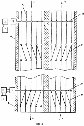
The device implementing this method is a source of electrical energy, a high-frequency converter, a monopolar high-voltage electrostatic generator of electric charges connected to a single-wire contact network consisting of a set of parallel wires installed above each lane of motorway and electric vehicles with retractable pantographs, each of which has Receiver, a diode unit, a DC-to-AC converter connected to the control unit and the electric motor of the electric motor. The essence of the proposed method of feeding electric vehicles and the device for its implementation is explained in FIG. 1, 2, 3. FIG. 1 shows the general scheme of the device implementing the claimed method of feeding electric vehicles.
 |
 |
 |
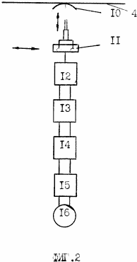
In Fig. 2 scheme for supplying electrical energy to the contact network. In Fig. 3 power supply circuit of an electric vehicle from a single-wire line of the contact network. The device comprises one or more electric power sources 1 which, through a high-frequency converter 2, and a monopolar high-voltage electrostatic generator of electrostatic charges 3 are connected to a contact network 4 consisting of a plurality of single-wire lines 5 located above each motorway in two directions 6 and 7 and connected in parallel with Using electrical jumpers 8, 9. |
The current collector 10 with the telescopic drive 11 is connected to the contact network 4 and the electric motor 16 of the electric vehicle through the receiving and matching device 12, the diode unit 13, the DC / AC converter 14 and the control unit 15.
Two outputs of the receiving and matching device 12 are connected to two inputs of the diode unit 13, two outputs of which are connected to a DC-to-AC converter 14 whose outputs are connected to the control unit 15, which in turn is connected to the valve motor 16.
The monopolar high-voltage electrostatic generator of electric charges 3 is made in the form of a Tesla monovibrator with a resonance frequency of 1-50 KHz and consists of a high-voltage 17 and low-voltage 18 windings wound on a common core 19, the low-voltage winding 18 being connected to a high-frequency converter 2. One terminal of the high-voltage winding 17 Is isolated, and the other is connected to the contact network 4.
METHOD REALIZES AS FOLLOWED
A monopolar high-voltage electrostatic electric charge generator 3 is connected to the electric power source 1 through a high-frequency converter 2, creating a unidirectional flow of electrical charges through a single-wire contact network 4 connected by bridges 8, 9 along directions 6, 7 to the current collector 10 with telescopic drive 11.
In the receiver-matching device 12, the diode unit 13, and the DC-to-AC converter 14, the electrical energy of the free electric charges is converted back to the AC electric power for power supply through the control unit 15 of the vehicle motor 16.
The use of the proposed method and the power supply device of the electric vehicle ensures an increase in efficiency, reliability of operation, an increase in the service life, a reduction in energy losses and the provision of multi-row movement of electric vehicles along the motorway.
By applying a high voltage single-wire line to the high-voltage input of the receiving and matching device, and the low voltage from the two outputs of the receiving and matching device after the DC-to-AC conversion is applied to the electric vehicle control unit.
CLAIM
1. A method for supplying electric vehicles, comprising: supplying electric power from a source of electric power through a high-frequency converter and a contact network over each lane to individual vehicle pantographs, characterized in that the electrical energy of the high-frequency converter is fed to a high-voltage electrostatic generator of electric charges obtained in the generator Electric charges are moved in a resonance mode by means of an electric field of the generator through a contact single-wire network and current collectors to each electric vehicle, and the inverse transformation of the energy of the electric field of free charges into electric energy of an alternating current is carried out by applying the voltage of a single-wire line to the input of the receiving and matching device.
2. A power supply device for electric vehicles comprising a source of electrical energy to which a high-frequency converter is connected, a contact network above each lane and individual electric current collectors connected thereto, characterized in that an unipolar high-voltage electrically connected to them is installed between the high-frequency converter and the contact network An electrostatic generator of electric charges, and each electric vehicle comprises a conversion device for converting the energy of the electric field of the free charges into a direct current or an alternating current of the required frequency.
3. The device according to claim 2, characterized in that the sections of the contact network installed in parallel over each lane in the forward and reverse directions of the electric vehicle movement and located at the same distance from the monopolar high-voltage electrostatic generator of electric charges have the same potential and electric field strength And connected by equipotential electrically conducting bridges, and high-voltage electrostatic generators of electric charges are installed along the contact network at a distance of 10 - 100 km from each other.
4. The device according to claim 3, characterized in that equipotential bridges between single-wire lines of the contact network are installed at an angle to these lines.
5. The device according to claim 2, characterized in that the monopolar high-voltage electrostatic generator of electric charges is made in the form of a Tesla monovibrator with a resonant frequency of 1-50 kHz.
6. Apparatus according to claim 2, characterized in that the current collectors of electric vehicles have telescopic mechanisms for outward extension in the vertical and horizontal direction.
7. The device according to claim 2, characterized in that the conversion device for converting the energy of the electric field of the free charges into alternating current of the necessary frequency is established on each electric vehicle and comprises a receiving and matching device in which one terminal of the primary winding is connected to the susceptor, and the second The output is isolated, the secondary winding is connected via a diode block, a DC to AC converter and a control unit with a gate motor of the electric vehicle.
print version
Publication date 16.02.2007gg
![]()

Comments
When commenting on, remember that the content and tone of your message can hurt the feelings of real people, show respect and tolerance to your interlocutors even if you do not share their opinion, your behavior in the conditions of freedom of expression and anonymity provided by the Internet, changes Not only virtual, but also the real world. All comments are hidden from the index, spam is controlled.