
Flat satellite dish
| Flat satellite dish |
|
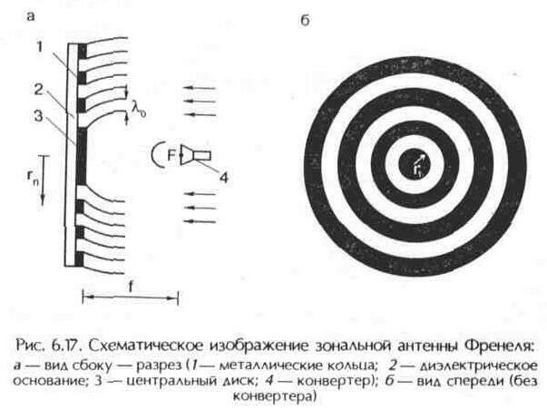
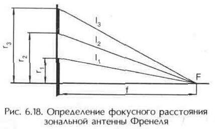
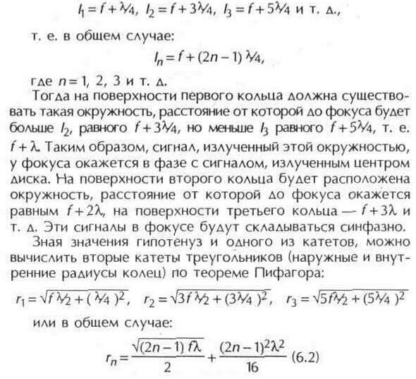
At present, two main paraboloid of revolution are most widely used in satellite direct television reception (SSTP) as antennas: Axisymmetric and offset. The laboriousness of manufacturing a parabolic reflector forced us to look for alternative designs of antennas that are more technological in production and self-manufacturing. Such constructions include the flat zone reflector of Fresnel (Figure 6.17). Auguste Jean Fresnel (1788-1828), a French physicist, one of the founders of wave optics, in the process of studying diffraction of light, used the method of dividing the wave front into annular zones, subsequently named after him. The zone Fresnel antenna (ZAP) by operation principle differs significantly from the commonly used antennas containing a parabolic reflector in the base. The description of the antenna and the method of its calculation are compiled by V. Nikitin (Moscow) and the author of this book. Antenna reflector Fresnel is a conductive concentric annular surface, located in the same plane. Under the influence of the incident wave of the electromagnetic field, according to the Huygens principle, each ring becomes a source of secondary radiation, Which is directed in different directions in contrast to the paraboloid of revolution, which reflects all the rays in the direction of the focus. It is possible to choose such a width of each ring of the zonal antenna and the distance between them so that signals of secondary radiation from the middle lines of each ring at a certain point of space coincide in phase. For this it is sufficient that the distances between the middle lines of the rings and the indicated point differ by the length Wave signals - l in . This point by analogy with a paraboloid can be called a focus. In the focus, as in the parabolic antenna, there is an irradiator. In Fig. 6.18 shows the cross section (side view) of the upper part of the central disk of the antenna and the first ring. If a point is selected as the focal point at a distance f from the plane with rings, then the signals emitted by the centers of the rings will coincide in phase in focus at the following values of the distances between the edges of the rings and the focus: The signals emitted by the middle of the rings are in phase with the signal emitted by the center of the disk. The phase-out between the signals emitted by the edge of the disc and its center, as well as the rim's edges and their center, is only 1/4 of the wavelength. Thus, the calculation of ZAP is limited to the choice of the location of the focus F on the imaginary axis of the antenna, i.e., the distance f from the antenna web, and the calculation of the inner and outer radii of the rings as a function of the wavelength of the repeater, using formula (6.2). The distance f is not critical And it is selected within 500 ... 1000 mm (for antennas of large diameters). The signals that radiate the rim edges differ in phase from the signals that the circle emits (located in the middle of the ring), which ensures in- phase . Broad rings provide broadband antennas. Due to the fact that the radii of the ZAP gauge depend on the wavelength of the signal, it may seem that the antenna is narrowband and for each frequency (or wavelength) of the satellite transponder, the corresponding ring sizes will be needed. However, calculations show that this is not so. If the radii of the rings are calculated for an average frequency range of 10.7 ... 11.7 GHz (wavelength
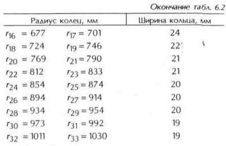
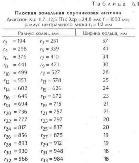
In Table.
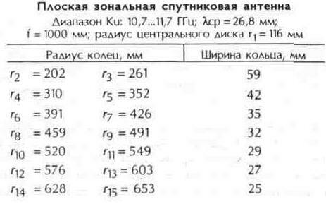
6.2, 6.3 shows the results of calculating the sizes of ZAF for the specified frequency bands.
In the formula (6.2), the order numbers of the radii were successively substituted (the even numbers correspond to the inner radii, the odd ones to the outer radii, and r1 the radius of the central disk).
The distance f from the central disk to the focus F is chosen equal to
Table 6.2. If we calculate the gauge radii for the average wavelength of the entire broadcasting range Ki (10.7 ... 12.75 GHz), on its edges these "in-phase" circles extend beyond the surface of the rings. Therefore, at the edges of such a wide range of in-phase addition of signals does not work. As a result of the calculation, the radii of the "in-phase" circles are obtained, where n is the number of the ring.
The central disk corresponds to n = 1. The width is chosen arbitrarily.
In practice, it is possible to make a central disk of radius
The zone antenna is flat in shape, so it is much more technologically advanced in amateur manufacturing conditions. Such an antenna can be made from a large piece of foil plastic or by etching, or by cutting gaps between rings. It can also be made by sticking rings of foil or flat sheet on a sheet of getinax , textolite, plexiglass, wood fiber cloth ( fiberboard ). To reduce the wind load in the dielectric base of the antenna, an arbitrary number of holes are drilled. The main disadvantage of a zonal antenna in comparison with a parabolic of the same diameter is the smaller gain, since not all of the energy of the signal entering the antenna web is directed to the irradiator. Under weak signal conditions, loss of amplification, even by 2 dB, leads to signal damage by noise and loss of color. To compensate for the lack of the gain factor of the CJSC, it is necessary to increase the diameter of the antenna web, although with sufficient satellite transponder power and large elevation angles (less thermal noise of the Earth affects) for such a reception point, such an antenna provides good results. The converter can be attached to the ZAF focus in the same way as for a direct- focus parabolic antenna |


Comments
When commenting on, remember that the content and tone of your message can hurt the feelings of real people, show respect and tolerance to your interlocutors even if you do not share their opinion, your behavior in the conditions of freedom of expression and anonymity provided by the Internet, changes Not only virtual, but also the real world. All comments are hidden from the index, spam is controlled.