Electronic dust collector
| Electronic dust collector |
|
Usually, complex and cumbersome mechanical filters having low productivity are used to purify air from dust. It is possible to increase the productivity and reduce the dimensions of the air-cleaning plants by using an electronic dust collector. The principle of operation of such a dust collector is that the polluted air passes through a metal pipe 1, inside which are installed two wire grids 2 and 3, playing the role of a filter (Fig. 1). Grid 2 is isolated from the box and is in relation to it under a constant positive voltage of 5.2 square meters. Grid z has a reliable electrical contact with the box (grounded). Dust particles, passing through the first grid, acquire a strong electric charge, which causes them to settle on the grid of the second filter, which has a negative potential in relation to the first grid. Puc.1 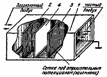 For cleaning large particles, an additional mechanical filter 4 is installed between the first and second filters. Dust-free clean air exits from the opposite tube hole and dust settles on the bottom near the second filter. The device of the electron dust collector is simple, but requires a constant voltage source of 5.2 square meters. It can be assembled according to the proposed scheme (see Figure 2). It is a rectifier of mains voltage, consisting of a step-up transformer Tp1 and a rectifier with a voltage doubling on diodes D1, D2 and capacitors C2, C3. Limitation of the output current to a safe value for a person of 5 mA is carried out by means of current-limiting resistors R1-R3, as well as an additional winding III, of the transformer Tr1 (together with the capacitor C1 it forms a ferro-resonant stabilizing circuit). Its effect is that if the rectified current exceeds 5 mA, the voltage at the terminals of the winding II decreases. Puc.2 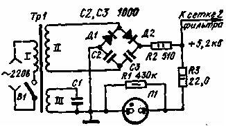 The neon lamp L1 in this device plays the role of an indicator of the magnitude of the rectified voltage. It turns on in parallel with resistor R1. Its resistance is selected so that when the rectified voltage is 5.2 kV, the voltage drop across the resistor R1 is about 100 V, that is, sufficient to ignite the neon lamp. As dust accumulates on the second grid, there is an increase in the current consumed, this leads to a decrease in the output voltage. L1 lamp goes out, which indicates that the dust collector needs cleaning. You can only clean the device after turning off the power. In the rectifier of the dust collector, silicon diode poles and high-voltage capacitors used in televisions are used. Transformer Тр1, with the purpose of increase of its electric strength, is filled with epoxy resin. As diodes D1 and D2, silicon high-voltage rectifying columns D1006-D1008 can be used. |

Comments
When commenting on, remember that the content and tone of your message can hurt the feelings of real people, show respect and tolerance to your interlocutors even if you do not share their opinion, your behavior in the conditions of freedom of expression and anonymity provided by the Internet, changes Not only virtual, but also the real world. All comments are hidden from the index, spam is controlled.