
Anti-theft engine malfunction simulator
Anti-theft engine malfunction simulator
The car thieves become extremely resourceful in finding and damaging anti-theft devices. And what if the engine periodically starts and stalls? If the car is equipped with equipment simulating a malfunction of the engine, the potential thief most likely will not suspect the operation of the anti-theft device and will look for a new victim.
The new device provides a normal engine start, and after 12 With opens the ignition coil circuit, causing the engine to stall. After 4 With the circuit once again locked, allowing the kidnapper to restart the engine. The cycle is repeated, and after another 12 With the engine stalling and not starting. By this time, the kidnapper, perhaps, will drive a short distance from the parking lot.
The kidnapper can get off the ground in a car equipped with this circuit, but he will soon give up his intentions after the engine has been stopped repeatedly. The timer IC periodically turns off the voltage from the ignition coil, simulating a motor malfunction.
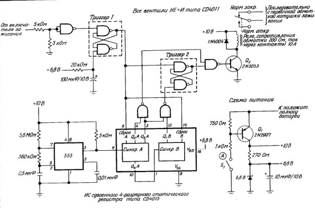
In the scheme of the anti-theft device, shown in Fig. 1, the IC 555 timers and K / MOS ICs, consuming a small current, are used. Leaving the car, the driver activates the device with a disguised Si switch. Non-smoking drivers can well disguise the Si switch in the lighter, whose wire is disconnected from the battery and connected to the circuit at point A. For additional protection, it is possible to connect the ignition switch in series with the Si switch.
After the circuit is set to the operating state by the Si switch, when the ignition is switched on, trigger 1 is triggered on two NE-AND valves, as a result, 0.5 Hz pulses from the 555 timer output go to the shift register CD 4015. The CD 4015 includes two four-bit Register, which in this case are connected in series. After 12 S (six pulses), the HE-I valves open the transistor Q2, which opens the normally closed relay contacts and thereby de-activates the motor. After two more timer pulses arrive in the shift register, the NAND gate closes the transistor Q2, allowing the engine to restart.
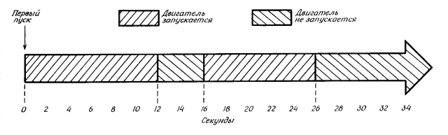
The cycle resumes, but when the ignition is turned on for the third time, trigger 2 starts and engine start is blocked until the driver that opens the Si switch opens. The time diagrams are shown in detail in Fig. 2.
The start- stop periods of the anti-theft scheme are 12 and 4, respectively from. After the engine stalls for the third time, it can not be started until the driver unlocks the Si switch disguised in the car's interior.
To make the device unlike the anti-theft facility, it can be assembled on a small board and placed in a housing reminiscent of a device for monitoring environmental contamination.
By connecting terminals 5 and 12 of the shift register to the additional two-input NO-AND valve, an alarm can be received after 60 from. The valve can control the relay, which includes a sound signal, headlights or a siren, if it is necessary to draw attention to the car being stolen.
Analogues of microcircuits: 555 - КР1006ВИ1 CD4011 - 561Л7 CD4015 - 561ИР2.

Comments
When commenting on, remember that the content and tone of your message can hurt the feelings of real people, show respect and tolerance to your interlocutors even if you do not share their opinion, your behavior in the conditions of freedom of expression and anonymity provided by the Internet, changes Not only virtual, but also the real world. All comments are hidden from the index, spam is controlled.