XEROX ON EACH TABLE
XEROX ON EACH TABLE
Judging by the announcements in the newspapers, their choice is the richest, only that prices are astronomical. Only a rich organization can afford it. And if the computer can still be assembled alone, you only have to dream of a copier. However, there is a way out! Whoever knows a little about radio engineering and photography, in a day or two, can collect a copying device, although not so perfect, but workable.
Xerography appeared several decades ago at the junction between photographic and electrostatics. It turned out that when an exposed paper is exposed, the charge configuration accurately follows the contours of the image, and its density depends on the intensity of the halftones. Spatter on such a sheet of paint, it will stick to electrified areas, and you have an exact copy of the image.
Installation, working on this principle, we propose to do. You will need a high constant voltage source to electrify the photosensitive material, photosensitive paper and developer with the paint.
Let's start with the preform of a photosensitive material. It is paper coated with a photoconductive emulsion. It is obtained by mixing 2 parts by weight of dry zinc white and one part of BF-2 glue. Thoroughly mix the mass by periodically adding alcohol. It should turn out to be similar in density to sour cream. Now the emulsion is slightly heated. It will become less viscous and it will fit well on the leaf. Paper should be better coated and coated with a thin layer of emulsion with a brush or roller. After letting the sheets dry for about 20 minutes, cover them with a second spoon. After the drying is finished at room temperature (about 2 hours), the paper is ready for photocopying. But while she is not sensitive to light.
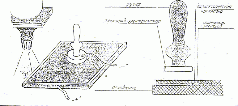
The surface layer of the photo-semiconductor must be informed of the electric charge. They do this in the dark, using an electrifier-electrode in the form of a metal disk (copper, brass) with a dielectric handle. The appearance of the electrifier and the installation is shown in the figure.
It consists of a dielectric base made of getinax, textolite or vinplast 5-6 mm thick. It is fastened with a copper or brass plate thickness
The electrode-electrifier is connected to the negative charge, and the plate on the base is connected to the positive pole of the converter. Pay special attention to the electrical insulation of current-carrying buses to the places of their attachment to the electrodes. MGHV wire for this purpose is not suitable, you need a wire type VMMA, MPI, and you can use a cable type RK-75, after removing the shielding from it. After switching on the high voltage source, swipe across the entire surface of the sheet. The paper is now ready for exposure. You can not bear it. After having prepared several sheets, start copying, otherwise the charge can "expire" and the material will lose photosensitivity.
To get a print on paper, you need to project the image. It is not difficult to do this with the help of a photo intensifier, or even better with an epidiaskcope. But remember that in xerography the process corresponds to the formula "positive-positive".
Exposure time at a light source with a power of 100-150 W from a distance
Now the turn of manifestation has come.
You can apply dry or wet methods.
But, of course, at home, the second is more convenient.
Dilute the thick ink for rotary machines in refined aviation or automotive gasoline in the proportion of 5 grams of paint on
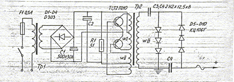
The design of the converter must be capable of providing a voltage of 10-15 kV at very low current. The simplest diagram of such a device is shown in the figure. The high voltage source shown in the diagram consists of a step-down network transformer . With a diode bridge, a converter and a voltage multiplier.
The rectified voltage from the network transformer Tp 1 is fed to the input of the self-excited transducer, assembled in a push-pull circuit on P210 type transistors. Their collector pins are connected to the winding I, and the terminals of the 6-phase are connected to the winding II . Resistor P 1 and capacitor C 2 provide the necessary mode of operation.
On the winding I leads, an alternating voltage of 3000-4000 Hz appears. It is raised hundreds of times by the secondary winding of the IRS and fed to a multiplication circuit consisting of high-voltage diodes KC106G and Capacitors of the filter type K73-13 with the capacity of 2200 pF and designed for a voltage of not less than 12 kV. The rectified voltage is applied to the photocopying unit.
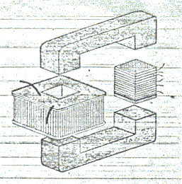
The step-up transformer Tr 2 is wound on a ferrite core from a television line transformer (TVS-A, TVS-B, TVS-110) consisting of two halves (see Fig.). The high-voltage winding III is wound on a frame laminated of fiberglass, electro-cardboard or plexiglas thick
Winding make a turn to the turn, isolating with a thin fluoroplastic film or lacotte each layer. Make sure that the coils of the upper layers do not touch the lower ones.
For primary windings, make a sleeve made of cardboard. Winding I contains 14 turns of PEL 0.6 wire, and winding II - 6 turns of the same wire with a tap from the middle. It is desirable to cover the windings with paraffin and wrap the tape .
In the frames, insert the core halves and tighten them with the fastener from the line transformer.
The step-up transformer can also be wound on a conventional iron core type Ш-20 with the thickness of the set
Transistors should preferably be installed on heat sinks with an area of 60-100 square meters. Cm from sheet duralumin or brass with a thickness of 1.5-2.0 mm.
The transducer parts are placed on a 3-5 mm thick getinax board and an insert of the case made of Plexiglas. When installing, pay special attention to the connection between diodes and capacitors. Connecting wires should be short, and soldering - smooth and smooth. All the sharp edges of the soldering and the protruding ends of the conductors are carefully rounded by the nafile, otherwise they will become a source of corona discharges.
The rectifier is assembled on a bridge circuit using diodes of the type D3O3-D3O5 or similar. The rectified voltage is filtered by capacitor C 1 . The alternating voltage is removed from the secondary winding of the step-down transformer Tp1. The primary winding is rated for 220 V. The rectifier is turned on by the toggle switch B 1 .
Network transformer Tr 1 is wound on a core of iron Sh-20 at a thickness of the set
The rectifier and the converter should be placed in a common housing. Pay special attention to the insulation of high-voltage terminals, from which high voltage is removed.
Verification and adjustment are reduced to several operations. First check the rectifier. Instead of a transducer, connect a 10 ohm resistor with a power of 20-25 W of type EW or C5-35 to it. Plug into the network and measure the voltage on the resistor - it must be at least 10 V.
Then connect the converter to the rectifier. If its circuit is correctly assembled and the parts are in order, a thin squeak of the high-voltage transformer will be heard. No - swap out the end leads of winding I or II . When there is a sharp crack or clicks of the breakdown, lower the supply voltage by soldering the rectifier to the secondary winding of the transformer Tp 1 with a lower voltage.
Make sure there are no corona discharges. Turn off the light in the room and take a look at the high-voltage part of the device. If purple flashes appear on the parts' conclusions, this is a sign of coronation . Its indispensable companion is the smell of ozone. Turn off the unit, inspect the soldering points, round off or reapply again.
Work on a photocopying machine requires special attention. High voltage is not dangerous in itself. The strength of the current is decisive. As is known, a current exceeding 30 μA is hazardous to life. But this does not mean that you can even accidentally touch current-carrying conductors. You will get a tangible shot spark spark!
And so the advice - with any repartition in the circuit, be sure to short- circuit the high- voltage multiplier wire to grounded output of winding III . All re-soldering during installation, conduct with the rectifier turned off from the network.


Comments
Commenting on, remember that the content and tone of your message can hurt the feelings of real people, show respect and tolerance to your interlocutors even if you do not share their opinion, your behavior in the conditions of freedom of expression and anonymity provided by the Internet, changes Not only virtual, but also the real world. All comments are hidden from the index, spam is controlled.