METAL PIPE
METAL PIPE
The device allows you to look for underground cables and metal pipelines of all kinds located at a depth of 1.5-
Structurally, the finder consists of two main units of the induction unit with mutually orthogonal (spaced along the axis) excitation and receiving frame antennas and an electronic unit into which the generator and receiver enter.
The frame antennas are located in a rigid cylinder with a diameter
In foreign pipe- cable detectors, the installation with vertical excitatory and horizontal receiving frame antennas prevailed. When moving such a device along a profile perpendicular to the cable or pipeline route, the curve of the change in the secondary induced signal is asymmetric and has two extreme values (maximum and minimum, and with phase- sensitive indication - two maxima) of different magnitude away from the cable route (pipeline). In order to determine the route, it is necessary to cross the profile twice in mutually opposite directions and make measurements on the terrain (determine the middle of the distance between the two marks). This device is free from this disadvantage: due to the location of the frame antennas at an angle of 45 0 and 135 0 to the horizon, it allows to obtain maximum indications directly above the object's path, and also to separate objects located parallel to each other at short distances in the horizontal plane (on the order of 1-
Schematic diagram
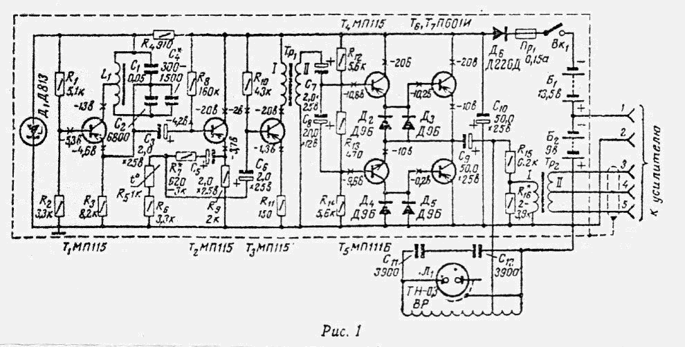
The electronic unit consists of a generator loaded with an excitation loop antenna and an amplifier with a receive loop antenna. The latter also includes a compensation device serving for fine (lasing) compensation of the primary induced signal (i.e., the signal induced directly from the excitation antenna to the receiver). The input of the compensation device is connected directly to the generator. Both units are powered by the batteries located in the generator block. The generator block (Fig. 1) consists of a master oscillator (T1), a cascade (T2), two amplifier stages (T3, T4, T5) and a power amplifier (T6, T7). The master oscillator, tuned to a frequency of 12 kHz , was assembled in a three-point circuit with a capacitive coupling. The coil L 1 of the oscillatory circuit is wound on a core of the TCHK-55P type and has an inductance of about 25 mg . The number of turns of the winding and the tap are selected during the adjustment.
To reduce the influence of the parameters of the transistor T 1 on the generation frequency, a partial inclusion of the circuit in the collector circuit is applied. The supply voltage of the master generator is stabilized by a stabilitron D 1 . The emitter follower, assembled on transistor T 2 , eliminates the effect of load changes on the master oscillator. The thermistor R 5 retains the necessary stability of the output voltage in the operating temperature range. Transformer Тр 1 - matching. The pre-term and output stages of the amplifier are made on transistors T4-T7 using a two- cycle transformerless transformer . The exciting loop antenna is connected through the capacitor C 9 to the transistors T6, T7. Diodes D2-D5 serve to prevent thermal breakdown of transistors T 6 , T 7 with increasing their temperature; To protect these transistors in the event of a short circuit of the output of the amplifier is the fuse Pr1 at a rated current of 0.15 A. From the generator output, the voltage is applied to the input of the compensation device via the voltage divider and the transformer Tp 2 . To facilitate electrical compensation, a polarity switch Tp 2 can be inserted into the device. The exciting VHF antenna is matched to the output resistance of the generator by means of partial switching. To increase the radiated power and reduce the non-linear distortion of the exciting signal, the antenna VR tunes in resonance to the operating frequency. To protect the generator from improperly turning on the batteries, diode D6 is installed. In the supply battery, the "Mars" type elements (373) are used to ensure continuous operation of the searcher for about 50 hours. When working with interruptions, the service life of the elements increases. The acquisition of the finder (see the diagram in Fig. 2) consists of a compensating device for the amplifier and a block of indicators.
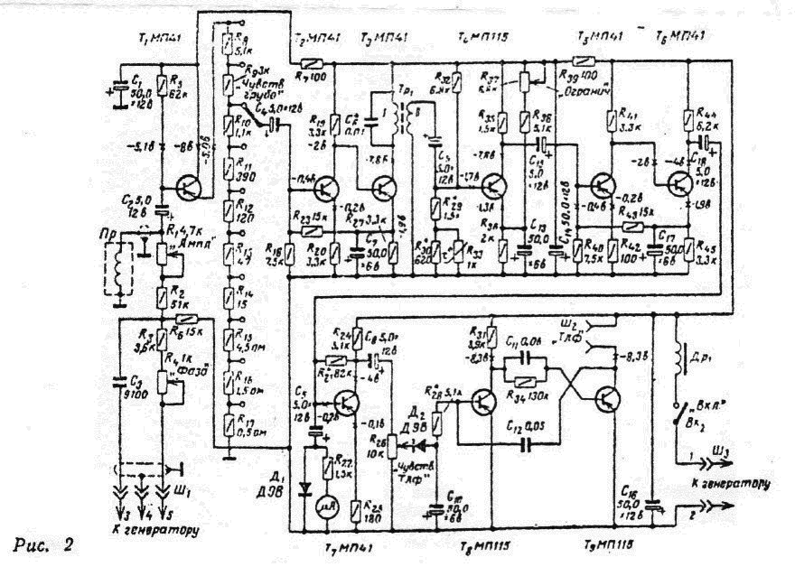
The main attenuation of the primary signal induced in the receiving frame antenna of the OL is due to its arrangement orthogonally and symmetrically with respect to the exciting loop antenna BP. The compensation device, connected together with the antenna PR to the input of the amplifier, serves to bring the residual primary signal to a level comparable to the secondary induced signal that appears when The seeker is approaching the desired metal objects. Adjustment of the amplitude and phase of the compensating voltage is carried out by the variable resistors R 1 and R 4, respectively. The amplifier contains six stages: the input on the transistor T 1 , the aperiodic (T2) resonant (T3), the limiter (T4), the two aperiodic (T5 and T6). The connection between transistors T 2 , T3 and T5, T6 is direct. In the indicator box, two types of indication are applied: visual (by microampere meter) and acoustic (by sound in telephones). The visual indication channel has a detector (diode D 1 ), to which a microammeter is connected per 100 μA , the acoustic indication channel consists of an amplifier (transistor T7), a detector (diode D2) and a multivibrator (transistors T8, T9). A voltage is applied to the base T8, detected by the diode D2. Its constant component is the bias voltage on the base of T8, which changes the frequency generated by the multivibrator, and consequently also the pitch of the phones.
The sensitivity of the amplifier can be adjusted roughly by the switch P 1 and the continuously variable resistor R 37, and the sensitivity of the acoustic indication channel by the variable resistor R 26. The cascade on the transistor T 4 is the limiting of the resulting signal (secondary and uncompensated primary) to a minimum. Such a limiter makes it possible to use an uncompensated primary signal whose amplitude is comparable to or greater than the amplitude of the secondary signal. As a result, irregular interference (eg, impulse) will be effectively suppressed. In addition, in the presence of a limiter, the requirements for the depth of compensation of the primary signal can be relaxed. Finally, the limiter allows to increase the sensitivity of the amplifier to small changes in the secondary signal and to facilitate the adjustment of the compensation device.
Design
The device consists of a housing in which the exciting and receiving frame antennas are located at an angle of 45 0 to the horizon; Bracket on which the housing with antennas is placed, as well as amplifier and generator blocks; A generator block with a power supply, an amplifier unit with a compensation device. The enclosure, in which the exciting and receiving frame antennas are fixed, is made of glass fiber reinforced plastic
Inside the cylinder along its axis, both the excitation and receiving frame antennas are inserted from both ends and fixed by means of brackets. Antennas to the brackets and bevels to the body are fixed with screws; After setting the device attachment points, pour epoxy resin. Antenna spacing along Axis of the cylinder (the distance between their centers) should be approximately
Customization.
The device is adjusted in the following order: first the loop antennas, then the compensator and finally the generator and amplifier. The adjustment of the loop antennas is reduced to adjusting their mutual arrangement until a minimum primary signal is obtained, measured in tens of microvolts. The found optimal position of the antennas is rigidly fixed by pouring fasteners with epoxy resin. To obtain the necessary depth of suppression of the primary signal (of the order of 100,000 times), one can use small adjustment frames or metal plates located near the receiving frame antenna. After adjustment, they are also filled with epoxy resin. Adjustment of the compensator reduces to a further reduction of the primary signal at the input of the amplifier by means of successive adjustments of the variable resistors R 1 and R 4. The tuning of the generator and amplifier does not have any specific features and therefore is not described here. When properly configured, the instrument generator must have the following parameters: operating frequency 12 kHz ± 60 Hz; Instability in the temperature range -20 0 - + 50 0 С - ± 120 Hz; The exciter frame quality is about 30; The active power, allocated in the excitation frame, is not less than 0.8 W; The instability of the output voltage in the temperature range -20 0 - +50 0 C - not worse than ± 5%. The parameters of the amplifier should be as follows: tuning frequency 12 kHz ± 120 Hz; Relative instability of the tuning frequency in the temperature range -20 0 - +50 0 С - about ± 2%, and the gain factor - about 2 times.


Comments
When commenting on, remember that the content and tone of your message can hurt the feelings of real people, show respect and tolerance to your interlocutors even if you do not share their opinion, your behavior in the conditions of freedom of expression and anonymity provided by the Internet, changes Not only virtual, but also the real world. All comments are hidden from the index, spam is controlled.