
Start-up device for car
To help car enthusiasts
The schemes shown in this section will be useful not only for motorists and will save a lot of money. Of course, some devices can be bought and manufactured, but there is not always the confidence in the quality of the product purchased. So, for example, commercially available automobile start-up devices are often not actually start-up due to their low power and without the help of a battery can not fulfill their task. But to make sure of this it is possible only after a while after the purchase.
There are also many useful electronic devices that our industry does not produce.
STARTING DEVICE
The application of the launcher will be especially useful for car enthusiasts engaged in car operation in the winter season, as it prolongs the life of the battery, and also makes it possible to start a cold car without problems in the winter, even if the battery is not fully charged. From experience it is known that at minus temperature the battery reduces its return by 25 ... 40%. And if it is not yet fully charged, it will not be able to provide the initial 200 A current required for starting the motor. This current consumes the starter at the initial moment of engine shaft unscrewing (the rated current of the starter's consumption is about 80 A, but at the start it is much larger).
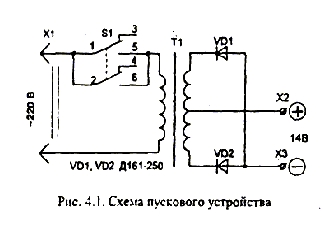
The simplest calculations show that . In order for the starter device to work effectively when it is connected in parallel with the battery, it must provide a current of at least 1 kVA at -10 ... 14 V. The rated power of the network transformer T1 (figure 4.1) must be at least 800 Tues. As is known, the rated working power of the transformer depends on the area of the magnetic circuit (iron) at the location of the windings.
The starter circuit itself is quite simple, but requires the correct manufacture of a network transformer.
It is convenient for him to use toroidal iron from any LATRA - at the same time, the minimum dimensions and weight of the device are obtained.
The perimeter of the section of iron can be from 230 to
Before winding the windings, it is necessary to round the file with sharp edges on the edges of the magnetic circuit, after which it is wrapped with a lacquer or a fiberglass cloth .
The primary winding of the transformer contains approximately 260 ... 290 turns of PEV-2 wire 1.5 ... 2.0 mm in diameter (the wire can be of any type with varnish insulation). The winding is distributed evenly into three layers, with interlaminar insulation. After the primary winding is completed, the transformer must be connected to the network and the idle current measured. It should be 200 ... 380 mA. In this case, there will be optimal conditions for the transformation of power into a secondary circuit. If the current is less, some of the windings should be rewound, if more - to be confused until the specified value is obtained. It should be taken into account that the relationship between the inductive resistance (and thus the current in the primary winding) and the number of turns is quadratic - even a slight change in the number of turns will lead to a significant change in the primary winding current.
When the transformer is operating in idling mode, there should be no heating. The heating of the winding indicates the presence of interturn closures or the pushing and closing of a part of the winding through the magnetic circuit. In this case, the winding will have to be done anew.
The secondary winding is wound with an insulated stranded copper conductor of at least 6 square meters. Mm (for example, type ПВКВ with rubber isolation) and contains two windings on 15 ... 18 coils. Secondary windings are wound simultaneously (two wires), which makes it easy to get their symmetry - the same voltage in both windings, which should be in the range of 12 ... 13.8 V at a nominal mains voltage of 220 V. Measure the voltage in the secondary winding better temporarily connected to Terminals X2, X3 load resistor with resistance 5 ... 10 Ohm.
The connection of rectifying diodes shown on the diagram allows the use of metal elements of the trigger body not only for fixing the diodes, but also as a heat sink without dielectric gaskets (plus a diode connected to a fixing nut).
To connect the starter device in parallel to the battery, the connecting wires must be insulated and stranded (preferably copper ones), with a cross section of at least 10 square meters. Mm (not to be confused with the diameter). At the ends of the wire, after maintenance, the connector tips are soldered.
Switch contacts S 1 must be rated for a current of at least 5 A , for example type T3.

Comments
When commenting on, remember that the content and tone of your message can hurt the feelings of real people, show respect and tolerance to your interlocutors even if you do not share their opinion, your behavior in the conditions of freedom of expression and anonymity provided by the Internet, changes Not only virtual, but also the real world. All comments are hidden from the index, spam is controlled.