RADIO STATION ON THREE TRANSISTORS.
RADIO ON THREE TRANSISTORS.
N. Marushkevich , Minsk
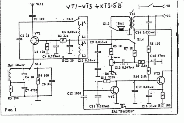
The radio station is designed for carrying out two-way communication in the range of 27 MHz with amplitude modulation. It is assembled on a transceiver circuit. The cascade on the transistor VT 1 serves both the receiver and the transmitter. The amplifier on transistors VT 1 and VT 2 in the receive mode amplifies the signal allocated by the receiver, and in the transmission mode modulates the carrier .
During installation, special attention should be paid to the arrangement of capacitors C10 and C11. They are used to prevent self-excitation. If self-excitation does occur, additional capacitors of the same capacity must be connected in addition.
About setup. It's very simple. First, using the frequency meter, the frequency of the transmitter is set, and then the receiver of another radio station is tuned for maximum noise suppression and the loudest signal volume. The transmitter L1 is tuned by the coil L 1, and the receiver L 2 is the receiver.
TECHNICAL DATA:
Supply voltage - 9-12 V.
The communication range in the open area is about
The current consumption of the receiver is 15 mA,
Transmitter - 30 mA.
Aerial telescopic -
0,7-
Body dimensions - 140x75x30 mm.
Тр 1 - any small-sized output transformer.
Wa 1 is any suitable size speaker with a winding resistance of 8-10 Ω.
Др 1 - ДПМ-0,6 or homemade: 75-80 turns PEV 0.1 on the resistor MLT 0,5 W - 500 kOhm.
The rest of the details are of any type.
Coils are wound on frames with a diameter
Printed circuit boards - In Fig. 2 Ð


Comments
When commenting on, remember that the content and tone of your message can hurt the feelings of real people, show respect and tolerance to your interlocutors even if you do not share their opinion, your behavior in the conditions of freedom of expression and anonymity provided by the Internet, changes Not only virtual, but also the real world. All comments are hidden from the index, spam is controlled.