
Solving the problems of commercial power losses
Electric power in the Russian Federation does not matter, but refers to one of the types of services supplied by power systems, and therefore theft of electricity is not considered property theft, and the power thief, if found theft, may suffer only administrative punishment, and the very fact of such theft is rather difficult to prove.
This state of affairs for a long time allowed us to work out mechanisms for the theft of electricity in very large quantities. So, according to the estimation of energy sales organizations in the private sector, the average power consumption in Russia is up to 60%, and in the municipal sector up to 25% of all electricity consumed by household consumers. Therefore, without new technical means of accounting for electricity consumption, some organizational measures can not cope with this problem.
If large and medium-sized enterprises have recently developed relatively reliable technical and commercial electricity metering systems that significantly reduce the possibility of its theft, then for household and small-engine consumers, especially in the private sector, the required electricity metering devices that protect against theft of electricity, a reduction in operating costs , Reliable in operation and maximally suitable for integration into automated systems of commercial metering of electric power of household consumers (ASKUE BP) until recently was not.
So the method of removing electricity meters to the facades of private houses or to power grid supports, recommended to reduce commercial losses in the private sector, has a number of drawbacks:
- Removal requires the installation of electricity meters in a securely protected box, with reliable grounding and quick disconnect devices when a person is exposed to voltage, requires the use of SIP, etc .;
- Do not solve the problem of calculating the balance of the received and consumed electricity;
- The problems of automation of information collection are not solved
ASKUE PP for communal housing, for example, the known system "Continium" solves the problem of ASKUE PP for communal housing, but since the data from the meter to the concentrator do not go digital, and in the form of telemetry pulses proportional to the power consumption, the loss of communication between the meter and The concentrator leads to a loss of electricity readings from the meter in proportion to the time of loss of communication.
Specialists of ZAO "RiM" in conjunction with Novosibirsk Energy Saving Foundation for Energy Conservation in the Novosibirsk region have developed a concept for accounting for electricity that formed the basis for the systems developed below.
The main thrust of these systems is:
- Reduction of commercial and technical losses of electric power;
- Reduction of operating costs;
- Calculation of the balance of electricity received and consumed.
At the same time, the household sector of electricity consumption can be divided into two subsectors, these are:
- Private (single-family houses, cottages);
- Communal (apartment buildings).
Proceeding from this, the development of electricity metering devices was carried out taking into account the specificity of electricity consumption in these subsectors.
The following main features are typical for the private housing sector:
- Large level of commercial power losses, up to 60%;
- Great difficulty in accessing the meter to verify readings or to check its technical condition.
For the communal housing sector, the following features are characteristic:
- Underestimation of meters when paying for electricity by consumers, commercial losses can reach up to 20%;
- Energy sales organizations do not have the ability to monitor the consumed and paid electricity;
- Difficulties in accessing the meter to verify the readings or to check its technical condition.
To solve these problems, AMR systems of the household sector were developed, which most fully took into account the peculiarities of each subsector-private and communal, such as PMC-2050 and PMC-2060b.
The PMC-2050 system is designed for the private sector and the solution of the following tasks:
- The metering devices must ensure that electricity is accounted for both in the authorized and unauthorized connection of the subscriber and make any unauthorized connections meaningless;
- Organize remote collection and subsequent centralized processing of accounting information on individual consumption of electricity by each consumer;
- Finding the meter must be in a private area , i.e. Responsibility for safety and serviceability of the device is borne by the subscriber (the electric power consumer);
- To ensure the calculation of the electricity balance for the set settlement day and hour.
For the practical implementation of these solutions, a set of hardware and software components included in the RMS-2050M system was developed:
- Single-phase multi-tariff counter - SOEB-2P DR with data transmission over the radio channel and protection against theft;
- Three-phase multi-tariff counter - STEB-04 / 2-80-DR with data transmission over the radio channel and protection against theft;
- Three-phase multi-tariff meter - STEB-04 / 1-7,5-P with data transmission over the radio channel for installation in the TP in order to obtain data for calculating the balance of consumed electricity;
- The portable reader of the controller is PMRM-2055RK. Receiving data over a radio channel, then transferring them to a computer via the RS-232 interface;
- Software with data transfer drivers to the existing Energy Sales database for further processing.
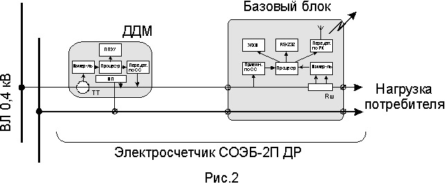
The meters with the anti-theft protection (single-phase and three-phase) are designed with an external remote (and) power sensor (DDM), which allowed to take control of the entire supply line to the subscriber starting from the 0.4 kV overhead line support. The structural diagram of the single-phase counter SOEB-2P DR simplified and extended is presented in Fig. 1 and Fig. 2, respectively, and the appearance on the photo1.
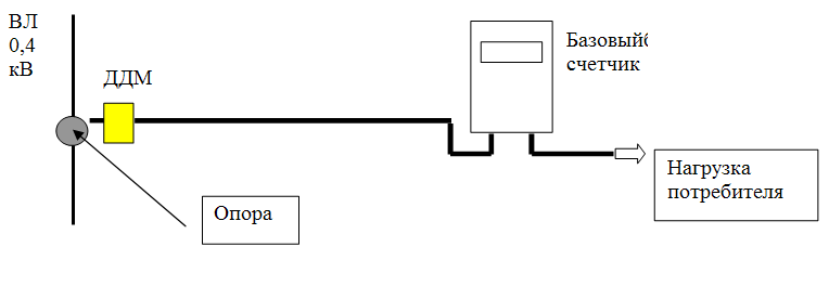
Fig.
1
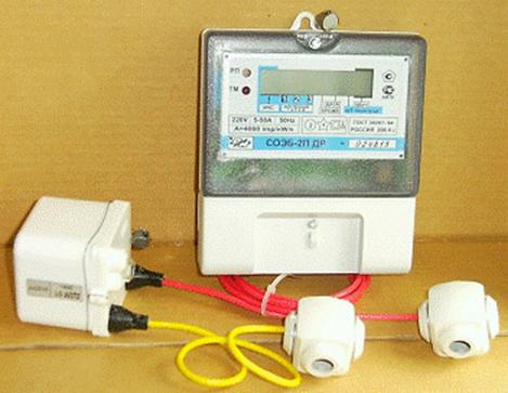
Fig.
2
Picture 1.
The principle of operation of the counter is based on the fact that the processor of the base unit (BB) analyzes data from the output of 2 meters, one of which is in the DDM, the second in the base unit and sums the data only from the meter that currently has the maximum measured power. The data from the DDM to the base unit is transmitted digitally over the power network, for this, the transmitter is located in the DDM. The principle of transmission is frequency shift keying (FSK). Transmission is carried out at 4 frequencies in the range 50 - 93 kHz. The confident range of transmission through the power channel is not less than 60 meters. The data from the counter via the radio channel is transmitted to the data transfer console (reader) PMRM-2055RK. The carrier frequency is 433.92 MHz, frequency shift keying (FSK), the transmitter power is not more than 10 MW. This provides a range of confident reception on the car antenna up to 100 meters.
Proceeding from the principle of the meter's operation, let's consider the main types of power theft:
- - Any impact separately on DDM or BB will cause an unbalance of data from DDM and BB and the data will be fed to the adder from the meter with the maximum output at the output. For example, the BB was shunted or a "sketch" was made on the supply wires, then the current passing through the DDM would be greater than through the BB (Iddm> IBB), the data to the adder would be taken from the DDM and vice versa, by shunting the DDM Iddm <IBB, the data in the adder would be taken from BB.
- - The counter is off, a temporary connection is made bypassing the counter, see Fig.3
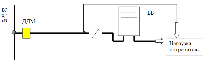
Fig. 3
Since DDM in such a scheme conducts the account of the consumed electric power, when the consumption scheme is restored, the data from the DDM will go to the base unit and will be added to the summing counter. Thus, data on consumption will not be lost, but will be taken into account in full. In addition, the operational log of the meter will display information about:
- Time on / off the counter;
- Amount of consumed kWh at tariffs before and after switching on;
- Status information before and after switching on.
In this way, you can conduct a full analysis of the consumption and operation modes of the meter.
Features of this type of meter:
- Two measuring channels;
- Self-diagnosis;
- LCD indicator with a temperature range of -36 ° C;
- Technological reserve according to the accuracy class;
- Resistance to climatic, mechanical and electromagnetic influences;
- Remote digital data transmission over a radio channel for a distance of up to 100 meters;
- Work at a voltage of the network 160 - 380 V.
Main characteristics of the meter:
- 1. Accuracy class according to GOST 30207-94 2.0;
- 2. Rated voltage, V 220 ± 20%;
- 3. Range of working currents, A 5 - 50;
- 4. Power detection of NSP, kVA, not less than 0.1;
- 5. Detection time, no more than, min. 5;
- 6. Transmitter power (433.92 MHz), mW 10;
- 7. Power consumption, VA is not more than 10;
- 8. Additional communication channels-radio channel; RS-232.
Counter functionality:
- Accounting and indication of the amount of electricity consumed by the cumulative total, separately for three tariffs;
- Accounting and indication of the amount of electricity consumed on the first day of the current month, separately for three tariffs;
- Automatic tariff switching;
- Indication of the current tariff;
- Automatic transition to "winter" and "summer" time;
- Fixing adjustments to the tariff schedule and the current time;
- Fixing the checksum of the tariff schedule;
- Accounting of the total operating time of the meter;
- Accumulation of data on the amount of electricity consumed, separately for three tariffs for the last 12 months in the internal log of the meter;
- Accumulation of operational data on the operating modes of the meter. Counter capacity is 79 records.
- Automatic daily clock correction (± 30 s / day);
- Data transmission over the radio channel to the mobile data transfer station PMRM-2055 RK.
The following information is transmitted:
- Own address;
- Electricity consumed by 3 tariffs as a cumulative total;
- Consumed electricity at 3 tariffs for the 1st day of the current month;
- Total operating time of the meter;
- Current date and time;
- Service information;
- The checksum.
MOBILE CONTROLLER CONTROLLER.
The mobile reader RMRM-2055 RK (see photo 2) is intended for reading data from electricity meters by radio channel, and transferring them to a PC. Additionally, in the counter, the reader will program the tariff schedule, record No. DDM, time correction and read the counter log through the RS-232 channel.
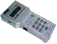
Photo.2
To simplify the work of the controller with the reader, there are three main modes:
- 1. Reception of data only from a specific counter number;
- 2. Receiving data from all the meters in the reception area (general reception);
- 3. Receiving data only from the specified counter numbers (selective reception).
In the latter case, the procedure is as follows. From the energy sales database, through the communication program with the reader, information is entered into the reader from which subscribers it is necessary to receive data. At the same time, the following data is entered for each subscriber: - the personal account, the counter number, the street name and the home number. And so on each route. Routes can be multiple and in each route you describe what counters you need to take. If for some reason the data from some counters is not received on the route, the controller on the reader's display will see which numbers have not been accepted, as well as the addresses of unregistered counters, in order to specifically understand what's happening. After receiving the data from all planned counters, the data via the communication program with the reader is downloaded to the energy sales organization's database for further processing.
The reader is a microprocessor unit that provides management of all device nodes, calendaring, storage, viewing and retrieval of accounting information in the reader database, as well as control of the radio receiver. All modes are set using the keyboard and are indicated on the LCD displays.
The main characteristics of the reader:
- 1. Memory capacity for 7000 subscribers;
- 2. Display on the LCD of all types of electricity consumption;
- 3. Communication time on the radio channel is not more than 30 seconds;
- 4. The range of radio reception is not less than 50 m, the car antenna is not less than 100 m;
- 5. The rate of exchange by RS-232 is not less than 9600 baud;
- 6. Power consumption no more than 1W;
- 7. The food is autonomous or from an external source.
Functionality:
- Selective reception of information from meters by radio channel;
- General reception of information on the radio channel;
- Radio search by number of the counter;
- View information on the database;
- Issuance of information on request from an external device via the RS-232 interface;
- Storage of received information with the power off (with integrated power elements of the console);
- Performance of technological functions (programming in the new tariff schedule, time correction, entry of DDM);
- Indication of the status of batteries;
- Charging of batteries installed instead of AA 1.5V;
- Additionally, the reader can be powered from the 12V vehicle's on-board network or through an external power supply from the 220V network.
The three-phase counter STEB-04 / 2-80-DR is constructed similarly to the single-phase SOEB-2P DR and has exactly the same functions, it is intended for installation in consumers having three-phase input.
Three-phase meter STEB-04 / 1-7,5-P for installation in transformer substations in order to ensure the calculation of the balance of electricity consumed. The appearance of the counter is presented in photo 3.
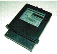
Photo 3
Features:
- Counters with the "K" index have an RS-485 interface, two-wire with an external power supply of 9 ... 12 V.
- Counters with the "P" index have a radio transmitter (433.93 MHz, 10 mW) for data transmission by the reader to the reader of the PMRM-2055RK. The communication range is not less than 50 m.
Functionality:
- By phase and total energy accounting - current and on the first day of the month;
- By phase and general measurement of average power for a period of 5 ... 30 min;
- Tariffication of consumption at three tariffs and six tariff zones;
- Automatic tariff switching;
- Indication of the current tariff;
- Automatic transition to summer or winter time;
- Accounting of the total operating time of the meter;
- Automatic daily clock adjustment;
- Maintenance of energy accounting journals by phase and total by months during the year;
- Maintenance of energy accounting journals by phase and total by day within a month;
- The following data is transmitted over the radio channel:
- The amounts of electricity consumed at the three tariffs are current and on the first day of the month;
- Total operating time of the meter;
- Current date and time;
- Number of the counter;
- Service information;
Technical specifications:
- Rated voltage - V 3'220
- The range of phase voltages is B 150 ... 400
- Rated current - A 5
- The maximum current is A 50 (7.5)
- Rated frequency - Hz 50
- Accuracy class - 1.0
- Range of radio communication - m 50
Software supplied by default:
- Program configuration and input of meters such as SOEB, STEB in operation;
- The program of service of the mobile reader of the controller.
The PMC-2060b system is intended for the municipal sector and the solution of the following tasks:
- (A) organize remote collection and subsequent centralized processing of accounting information on individual consumption of electricity by each consumer;
- (B) The location of the meter must be in a private area, for example, in an apartment or on a closed part of a landing; Responsibility for safety and serviceability of the device is borne by the subscriber (the electric power consumer);
- (C) The system should not require the laying of additional communication lines (or require a minimum number of such lines);
- (D) The system should take into account the common house and apartment consumption with the possibility of detecting unauthorized connections;
- (E) Ensure the calculation of the electricity balance for the set settlement day and hour.
At the same time, the task should be solved in such a way that ordinary linear personnel can perform the installation of the system as a routine replacement of meters.
For the practical implementation of these solutions, a set of hardware and software components are included in the lower level of the system:
- Electronic single-phase electricity meter SOEB-2PK-01 with remote transmission of data on power wires;
- Electronic single-phase multi-tariff electricity meter SO-2PK with remote indication of power wires;
- Electronic three-phase multi-tariff electricity meter STEB 04-7,5-1K with remote transmission of readings via RS485 interface and the possibility of phase-by-phase metering of consumed electricity;
- The device for data collection and transmission RM-USPD 2064M, which includes:
- The receiver of the data on a power network and on interface RS485;
- Cellular GSM / GPRS modem;
- The device for data collection and transmission of RM-USPD 2064, differing from the RM-USPD 2064M by the absence of a GSM / GPRS modem;
- The software includes:
- Program configuration and input of meters such as SOEB, STEB in operation;
- A top-level program designed for system configuration, collection and preliminary processing of information.
The structural scheme of the system per one block of flats is shown in Fig. 4
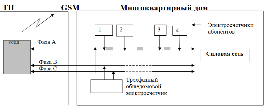
Fig.
4
The system presented in Fig. 4 has in its composition the minimum number of constituent elements, i.e. Directly the electric meter itself with the built-in transmitter over the power network and the USPD (data collection and transmission device). The data from the DRC via the integrated GSM-modem are transmitted directly to the computer connected to the power supply, see Fig.
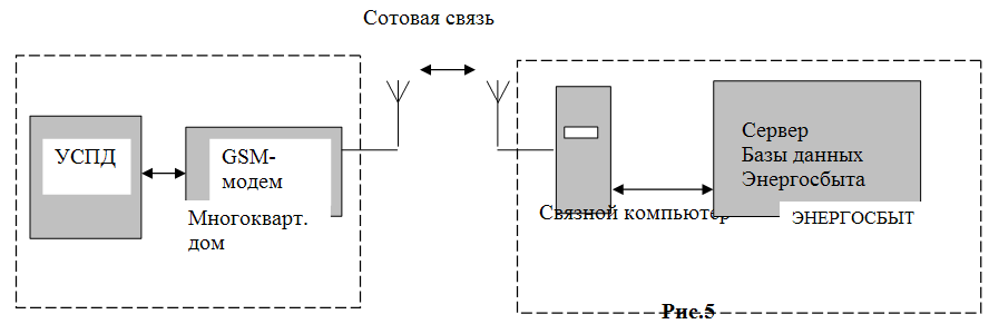
Fig.
5
Thus, the usual linear electrical personnel who service meters can install the system on the house. After the installation of meters and the transmission of the compliance data No. counter No. of the apartment from the connected computer, the system is activated, i.e. These data are reported in the USPD and the system is ready for operation. Data from the DRC are transmitted to the communication computer at the request of the latter.
Electricity meter SO-2PK
The instruments for the registration of the SOEB-2PK are installed in place of the existing induction meters and are intended for commercial metering of electricity consumption up to three tariffs and transmission of data on the power consumed by the subscriber over power wires to the USPD.
The main characteristics of the meter.
- Rated voltage, V 220 ± 20%;
- Rated current, A 5;
- Maximum current, A 60;
- Accuracy class 1 or 2;
- Power consumption, VA 10.
- Operating temperature range, ° C -25 ... + 50.
- The meter can be programmed to account for electricity at one, two or three tariffs, in accordance with the established tariff schedule, consisting of 6 tariff zones.
- The counter for the power network transmits the following data:
- Own serial number;
- Date and time of transmission by internal real-time clock;
- The amount of electricity accrual;
- The amount of energy consumed on the 1st day of the current month for each of the three tariffs;
- Service information.
- The transmission range of the power network is up to 200 m within one phase of one connection. The principle of data transmission over the power network is frequency shift keying (FSK). To increase noise immunity, the transmission is carried out at 4 frequencies in the range 50 - 93 kHz
The device for data collection and transmission RM-USPD 2064M.
The RM-USPD 2063 data collection and transmission device is designed to receive power grid data from the SOEB-2PK-type meters, receive and control data via the RS485 interface, and to exchange information on cellular communications with the central server of Energosbyt. The USPD is installed in the electrical house and is connected to a three-phase network. Three-phase meters, taking into account the total consumption and consumption of MOSFETs, lifts, sub-subscribers, etc., are connected to the DRC via the RS485 interface. The RS485 interface is powered by the USPD.
Main characteristics of the USPD:
- Maximum number of subscribers served 256
- Maximum receiving range by power network 300m
- The maximum number of phases from which information is collected, 3
- The maximum number of devices connected to the RS485 interface, 32
Counter STEB-04-7,5-1K
The STEB-04-7,5-1K meters are installed in place of existing three-phase meters and are intended for commercial metering of electricity consumption at three tariffs and transmission of data on the electricity consumed by the subscriber via the RS485 interface to the USPD RM-USPD 2064M. The indirect switch is used in conjunction with current transformers, the choice of which depends on the power consumption of electricity in a particular connection. Counters are used to account for total electricity, as well as for accounting for consumption of common areas, elevators, smoke exhaust systems, etc.
Main characteristics of the meter:
- Rated voltage, V 220/380 ± 20%;
- Rated current, A 5;
- The maximum current, A 7.5;
- Accuracy class 1;
- Power consumption, VA 10.
- Operating temperature range, ° C -25 ... + 50.
- The meter can be programmed to account for electricity at one, two or three tariffs, changing in accordance with the established tariff schedule consisting of 6 tariff zones.
- The meter transmits a wide range of data via the RS485 interface, among which the current consumption for the three tariffs is current and for the first day of the current month separately for each phase and the total, load profile, etc.
SOFTWARE
The software, supplied as part of the system, is designed to work in the "WINDOWS-2000 / XP / 2003" environment and provides data collection from subscriber counters in the MS SQL Server database. The software allows you to collect data on consumed electricity, both in the scale of the house and in the city. Data collection is possible via the following communication channels: RS-485, GSM (data transmission) and GPRS. Processing of collected data, balance of consumption. Analysis of collected data. Output of the result in a tabular and graphical form. Ability to export to Excel spreadsheets. Access to the database on the LAN with a differentiation of powers.
The most widely used system was the RMS-2050, because It is used in the private sector, where the largest commercial losses. The system is operated and tested as a pilot project in 19 cities of Russia and in many regions showed the economic effect of the introduction, while not only the unbalance of electricity is sharply reduced, but the load on transformer substations is also reduced. As the experience of the system's application shows, the solvency of the population (the level of collection of money) remains at the same level, and the unbalance in electricity reaches the level of technical losses.

Comments
Commenting on, remember that the content and tone of your message can hurt the feelings of real people, show respect and tolerance to your interlocutors even if you do not share their opinion, your behavior in the conditions of freedom of expression and anonymity provided by the Internet, changes Not only virtual, but also the real world. All comments are hidden from the index, spam is controlled.