Here you can find a large number of radio electronic circuits, radio amateur designs, information on electricity meters and much more.
- The principle of the induction electric meter.
- Schemes of connection of electric meters and their verification, description of schemes.
- Basic definitions (rated voltage and current of the meter, sensitivity of the counter, gear ratio and meter constant, meter error)
The principle of the single-phase active energy induction meter.
The meter is a measuring wattmeter system and is an integrating (summing) electrical measuring instrument. The principle of operation of induction devices is based on the interaction of alternating magnetic fluxes with currents induced by them in the moving part of the device (in the disk). Electromechanical forces of interaction cause movement of the moving part. A schematic arrangement of a single-phase counter is shown in Fig.
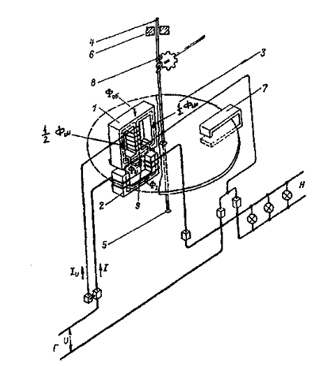
Its main components are electromagnets 1 and 2, an aluminum disk 3 fixed on the axis 4, axle bearings - a thrust bearing 5 and a bearing 6, a permanent magnet 7. The counting mechanism is connected to the axis by means of a gear mechanism 8 (not shown in the figure), 9 - In contrast to electromagnet 1. Electromagnet 1 contains an Ш-shaped magnetic circuit, on the middle rod of which there is a multi-turn coil from a thin wire connected to the voltage of the network U parallel to load H. This winding is in accordance with the switching scheme called a parallel winding or a voltage winding. At a nominal voltage of 220 V, the parallel winding usually has 8-12 thousand turns of wire with a diameter of 0.1 - 0.15 mm. The electromagnet 2 is located under the magnetic circuit of the voltage circuit and contains a U-shaped magnetic circuit with a coil of thick wire with a small coil Number of turns. This winding is connected in series with the load and is therefore called a series or current winding. Through it flows the total load current /. Usually the number of ampere-turns of this winding is in the range of 70 - 150, i.е. At a rated current of 5 A, the winding contains 14 to 30 turns. A set of parts consisting of a series and parallel windings with their magnetic circuits is called the rotating element of the meter.
The current flowing through the voltage winding creates a common alternating matt flow of the voltage circuit, a small part of which (working flow) suppresses the aluminum disk located in the gap between the two electromagnets. Most of the magnetic flux of the voltage circuit is closed through shunts and side rods of the magnetic circuit (a non-working flow), which is divided into two parts and is necessary to create the required phase angle between the magnetic fluxes of the voltage circuit and the load circuit (current circuit). The magnetic flux of the voltage circuit is directly proportional to the applied voltage (mains voltage).
The load current flowing through the current winding creates an alternating magnetic flux that also traverses the aluminum disk and closes along the magnetic shunt of the upper magnetic core and partly through the lateral rods. An insignificant part (a non-working stream) is closed through a counter to the disk. Since the magnetic circuit of the current winding has a U-shaped design, its magnetic flux crosses the disk twice.
Thus, only three variables of the magnetic flux pass through the counter disk. According to the law of electromagnetic induction, the variable magnetic fluxes of both windings at the intersection of the disk, induce in it the EMF (each of its own ie two), under the action of which in the disk around the traces of these flows the corresponding eddy currents flow (the rule of "drill bit" is remembered). As a result of the interaction of the magnetic flux of the voltage winding and the eddy current from the magnetic flux of the current winding and from the other side of the magnetic flux of the current winding and the vortex current from the voltage winding, there are electromechanical forces that create a torque acting on the disk. This moment is proportional to the product of these magnetic fluxes and the sine of the phase angle between them.
The active power consumed by the load is defined as the product of the current strength by the applied voltage and by the cosine of the angle between them. Since the magnetic fluxes of both windings are proportional to the voltage and current, it is possible to achieve constructively the equality of the sine of the angle between the currents and the cosine of the angle between the current and voltage vector to realize the proportionality of the torque of the counter with the coefficient of the measured active power. The sine of one angle is equal to the cosine of the other angle if there is a shift of 90 degrees between them, which is achieved in the design of the counters (using short-circuited turns, additional windings closed for controlled resistance, moving the screw clamp, etc.) The torque proportional to the power of the network drives the counter disk In the rotation, the speed of which is set when the torque is balanced by the braking torque. To create a braking torque in the meter there is a permanent magnet, which covers the poles with its poles. The lines of force of the magnetic field, intersecting the disk, induce in it an additional EMF proportional to the frequency of rotation of the disk. This EMF in turn causes a vortex current to flow in the disk, the interaction of which with the flow of a permanent magnet leads to the appearance of an electromechanical force directed against the movement of the disk, i.e. Leads to the creation of a braking torque. The adjustment of the braking torque, and therefore the rotational speed of the disk, is carried out by moving the permanent magnet in the radial direction. When the magnet approaches the center of the disk, the speed of rotation decreases.
Thus, having achieved a constant rotational speed of the counter disk, we obtain that the quantity of energy measured by the counter is obtained from the product of the number of revolutions of the counter disk and C-coefficient. Proportionality, constant counter.
ON TOP ^^
The principle of the single-phase electronic active energy meter.
The counter is an analog-to-digital device with preliminary conversion of power into an analog signal with the subsequent conversion of an analog signal to a pulse repetition rate, the summation of which gives the amount of energy consumed.
Structurally, the meter consists of a housing, a measuring current transformer and a converter on the printed circuit board and a charging module. Structurally, the counter consists of the following nodes:
• LCD driver
• secondary power source
• microcontroller
• Optical port
• memory
• converter
• Supervisor
• telemetry output
• Real-time clock
The converter is an analog-to-digital device with preliminary conversion of power into an analog signal using the PWM-AIM method, and then converting the analog signal into a pulse signal proportional to the consumed electricity. The secondary power source converts the variable input voltage to the value necessary for supplying all the nodes of the counter. The microcontroller calculates input pulses, calculates the energy consumed, controls and exchanges information with other nodes and meter circuits. The supervisor generates a reset signal when the power is turned on and off, and also generates a power failure signal when the input voltage drops. The memory stores data on consumed electricity and other parameters. The real-time clock is used to count the current time and date. The LCD driver receives information from the microcontroller and outputs the control signals to the LCD. The LCD is a multi-digit indicator and is intended for indicating the operating modes, information about the consumed electricity and time parameters. The optical port is designed for reading the readings and programming the counter. The microcontroller receives signals from the buttons on the meter panel and the signals from the converter are proportional to the consumption of electricity. The microcontroller stores the information in memory and provides a pulse signal about the power consumption to the telemetry output.
ON TOP ^^
SCHEMES OF INCLUSION OF COUNTERS AND THEIR CHECK. DESCRIPTION OF SCHEMES
The counter is an instrument that reacts not only to the energy value, but also to the direction of its transmission. The property of the counter to react to the direction of energy leads to the mandatory need to include the current circuit of the counter and the voltage circuit in a consistent manner, so that, with a positive energy direction, the disk rotates in accordance with the arrow. Before considering specific schemes for including counters, we list several general provisions
The terminals of the current winding of the meter and the voltage windings connected on the power supply side are conditionally called unipolar. In the circuits, unipolar conclusions of the windings of the meter (the beginning of the windings) are denoted by an asterisk. A unipolar voltage circuit terminal is always located next to the corresponding terminal of the current winding and at the direct-on counters it is connected to the current terminal by a removable jumper.
Earlier, when describing the counters, it was noted that the terminals of the current windings are denoted by the letters Г (the generator) and Н (load). In this case, the generator terminal corresponds to the beginning of the winding, and the load terminal to its end. When connecting the meter, it must be ensured that the current flows through the current windings from their beginnings to the ends. To do this, the wires from the power supply side must be connected to the generator terminals (terminals D) of the windings, and the wires leaving the counter to the load side must be connected to the load terminals (terminals H). For meters connected with measuring transformers, the polarity of both the TT and the TN must be taken into account. This is especially important for three-phase meters having complex switching circuits when the wrong polarity of the measuring transformers is not always immediately detected on the operating counter. If the meter is switched on via the CT, then the wire from the terminal of the secondary CT winding that is unipolar with the primary terminal is connected to the beginning of the current winding Winding connected to the power supply side. With this switching on, the current direction in the current winding will be the same as for direct connection. For three-phase meters, the input terminals of the voltage circuits, unipolar with the generator terminals of the current windings, are denoted by the numerals 1, 2, 3. This determines the specified order of phases 1- 2-3 when connecting meters. It should be noted that when connected, the internal connection scheme should not cause any doubt or ambiguity, since all the required internal connections are made in the manufacture of meters. It is important to monitor only the correctness of external connections. Fig. A.6.c shows typical schemes for the inclusion of active and reactive energy meters, both when they are directly connected to the electrical network, or with measuring transformers. Figs. A, b, c show schematic diagrams for the inclusion of a single-phase active energy meter with indication of the polarity of the measuring transformers. The secondary windings of CTs and VTs are grounded for safety reasons. In principle, it does not matter what to ground - the beginning or ends of the windings of the measuring transformers.
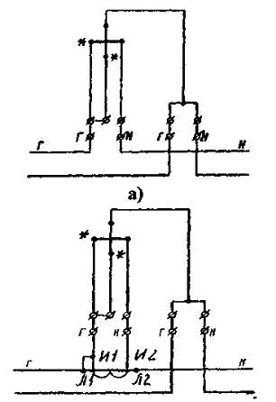
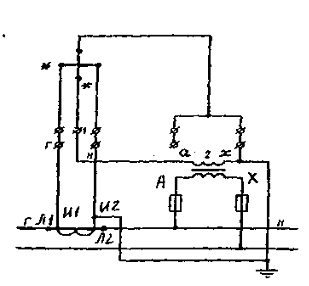
Fig. Schemes for the inclusion of a single-phase active energy meter: a - with direct connection; B - with semi-indirect inclusion in - with indirect connection;
Schematic diagrams for the inclusion of a three-phase three-wire, two-element active energy meter of the SAZ (SAZU) type are shown in Fig. a B C. Here we should especially note that the middle phase must be connected to the terminal with the number 2; The phase whose current is not supplied to the counter. When the meter is switched on with the VT, the clamp of this phase is grounded. In the circuit in Fig. 1, at T1, clamps are connected to the power supply side (i.e., clamps. And 1), but it would be possible to ground clamps on the load side as well. The CAS-type meters are mainly used with measuring transformers, and therefore the circuit shown in Fig. In is the main one when taking into account active energy in electric networks of 6 kV and higher.
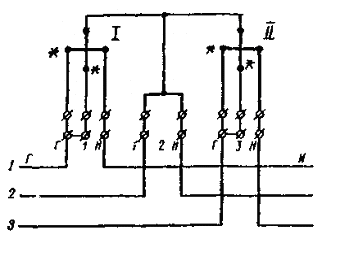
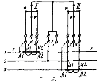
Fig. Schemes for the inclusion of a three-phase three-wire two-element active energy meter of the SAZ (SAZU) type:
A - with direct connection;
B - with semiclass inclusion;
C - with indirect inclusion
Principal electrical circuits for the inclusion of a three-phase three-element active energy meter of the type CA4 (CA4Y) are shown in Fig. A, b, c show the three-wire circuit, and Fig. R, q is a four-wire counter.
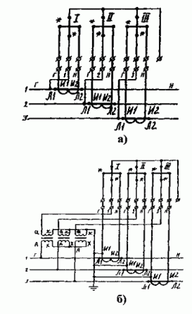
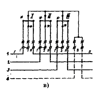
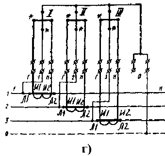
Fig. Schemes of inclusion of three-phase three-element active energy meter of type CA4 (CA4U):
A - with a semi-wired connection to a three-wire network;
B - if indirectly connected to a three-wire network;
C - when directly connected to a four-wire network;
G - with semi-inclosure, four-way network
In Fig. The circuit is shown with three single-phase VTs, the primary and secondary windings of which are connected to a star. In this case, the common point of the secondary windings is grounded for safety reasons. The same applies to the secondary windings of TT. In Fig. C, d, it is necessary to pay attention to the presence of a mandatory connection of the zero conductor of the network to the zero terminal (0) of the counter. It was noted above that the absence of such a connection can cause an additional error when taking energy into account in networks with asymmetry of voltages. Schemes for the inclusion of reactive energy meters with a 90-shift CP4 (CP4U) type in a four-wire network are shown in Fig. a B C. The order of supply of voltages and currents to the counter is the same as for the active energy meter. The scheme of indirect inclusion of the same counter in a three-wire network is shown in Fig. Since there is no TT in the middle phase of the network, instead of current Ib to the current winding of the second element of the counter, a geometric sum of the currents Ia + Ic, which, as is known, is equal to -Ib.
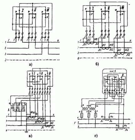
Fig. Schemes for the inclusion of a three-element reactive energy meter with a 90 ° shift of the type CP4 (CP4U):
A - when directly connected to a four-wire network;
B - when half-buried in a four-wire network;
C - if indirectly connected to a four-wire network;
G - if indirectly connected to a three-wire network
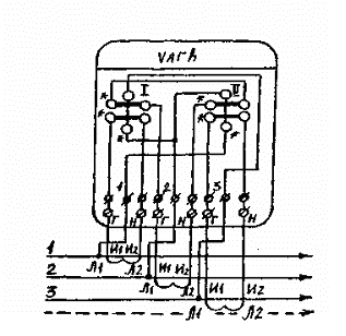
In Fig. A scheme is shown for the semiclassical inclusion of a two-element reactive energy counter with separated series windings of the type CP4 (CP4U) into a four-wire network.
In three-wire networks, where there are only two TTs, this counter can be switched on using the geometrical sum of the currents of the two phases in the same way as in Fig. D. In Fig. Schemes for the inclusion of a reactive energy meter such as SRZ (SRS) with a 60 ° shift to a three-wire network are presented.
Fig. Scheme of semi-indirect inclusion of a two-element reactive energy meter with separated consecutive windings of the type CP4 (CP4U) into a four-wire network
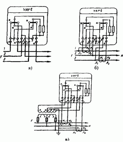
Fig. Scheme of inclusion of a two-element reactive energy meter of SRZ type (SRS) with a 60th shift to a three-wire network:
A - with direct connection;
B) semi-cosched;
C - with indirect inclusion
In view of the fact that active and reactive energy meters are commonly used together, in Fig. As an example, schemes for their joint inclusion are given. In Fig. Schemes of semi-indirect switching of meters into a four-wire network (380/220 V) are given. The circuit in Fig.
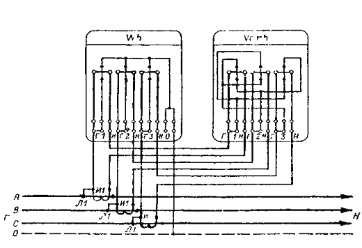
Fig. Scheme of semiclassical inclusion of three-element counters of active and reactive energy in a four-wire network with combined circuits of current and voltage.
Quantity of wire or control cable. When assembling it, the risk of incorrect inclusion of the counters is significantly reduced, since the phase (A, B, C) mismatches the current and voltage. Check the correctness of the circuit can be simplified methods without removing the vector diagram. To do this, it is sufficient to measure phase voltages, determine the order of phases and check the correctness of the inclusion of current circuits by alternately outputting two counter elements from work and fixing the correct rotation of the disk. The drawback of the circuit is that checking the correctness of the inclusion of current circuits requires three times Disconnect consumers and take special safety measures in the production process, since the secondary CT circuits are under the potentials of the phases of the primary network. Another serious drawback of the scheme in question is that its use is in conflict with the EMP (§ 1.7..46), which refers to the need to zero or ground the secondary windings of the measuring transformers. In contrast to the previous scheme in Fig. Has separate circuits of current and voltage, therefore it allows to check the correctness of the inclusion of meters and their replacement without switching off consumers, since in this circuit the circuits can be disconnected. In addition, it complies with the requirements of the Electrical Assemblies for the deletion and earthing of secondary CT windings.
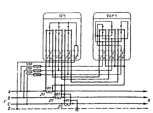
Fig. Scheme of semiclassical inclusion of three-element active and reactive energy meters in a four-wire network with separate circuits of current and voltage.
In Fig. The scheme of indirect inclusion of meters in a network over 1 kV is shown. In this scheme, as a reactive energy counter, a two-element four-wire counter with divided consecutive windings is adopted. It was mentioned above that since there is no TT in the middle phase of the network, instead of the current Ib,
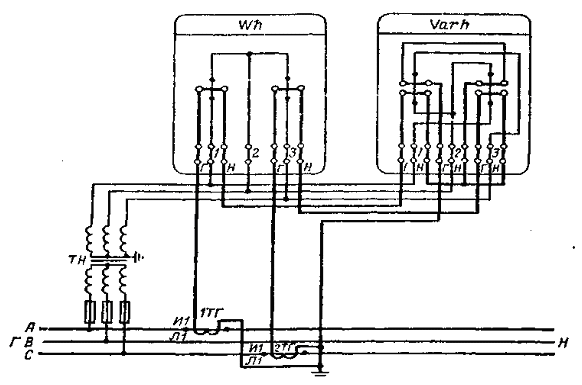
Fig. Scheme of indirect inclusion of two-element active and reactive energy meters in a three-wire network of more than 1 kV.
Corresponding to the current windings of this counter, the geometric sum of the currents Ia + Ic is equal to -Id. Instead of this reactive energy meter, a 90-degree counter can be used in this scheme. In this case, the geometrical sum of the currents Ia + Ic is also applied to the current winding of the second element. In Fig. The switching circuit is shown using a three-phase LV of the type NTMI, in which the secondary winding is grounded. In practice, a three-phase VT can be used and the grounding of the secondary winding of phase B can also be used. Instead of a three-phase VT, two single-phase VTs connected via an open triangle circuit can also be used. In conclusion, we note that the switch-on circuit of the meter is usually applied to the cover of the clamping box. However, under operating conditions, the cover can be removed from the counter of a different type. Therefore, it is always necessary to verify the reliability of the circuit by reconciling it with a typical circuit and marking the terminals.
ON TOP ^^
Basic concepts and definitions associated with the design and maintenance of electricity metering circuits.
The main purpose of electricity metering is to obtain reliable information about the amount of electricity and capacity produced, its transmission, distribution and consumption in the wholesale market and the retail consumption market for the solution of the following technical and economic tasks at all levels of management in the energy sector:
• financial calculations for electricity and capacity between the wholesale and retail market participants
• control of power consumption modes
• determination and prognosis of all components of the electricity balance (generation, leave from the bus, loss, etc.)
• Determining the cost and cost of production, transmission, distribution of electricity and capacity
• control of the technical condition and compliance with the requirements of regulatory and technical documents of electricity metering systems in facilities
The rated voltage and rated current of three-phase meters are indicated as the product of the number of phases by the nominal values of voltage and current, with the voltage being assumed to be linear, for example: 3 * 5; 3 * 380 V. Three-phase four-wire meters indicate the linear and phase voltages, separated from each other by a slash, for example: 3 * 5 A; 3 * 380/220 V. Transformer counters specify the nominal transformation ratios: 3 * 6000/100 V; 3 * 200/5 A. On the front panels of the direct-on counters, in addition to the rated current, the maximum current value (usually in parentheses) is indicated: 5-20 A or 5 (20) A.
To the meter, in addition to the requirement of no self-propulsion, the requirement is also for the presence of sensitivity , which is determined by the lowest value of the current, expressed as a percentage of the nominal value, at a nominal voltage and cos f = 1, which causes the disk to rotate without stopping. At the same time, no more than two rollers of the counting mechanism can be moved simultaneously. The threshold of sensitivity on should exceed: 0.3% for meters of accuracy class 0.5; 0.4% for accuracy class 1.0; 0.46% for single-phase meters of accuracy class 2.0; 0.5% for three-phase accuracy classes 1.5 and 2.0. The sensitivity threshold of accuracy class 0.5, equipped with a backstop, should not exceed 0.4% of the rated current.
The transfer number of the counter is the number of revolutions of its disk, corresponding to the unit of energy being measured. The gear ratio is indicated on the front panel of the meter with an inscription, for example: 1 kWh = 1280 revolutions of the disc.
The counter constant indicates the number of units of electricity that the meter takes into account for one revolution of the disk. It is customary to determine the counter constant as the number of watt-seconds per revolution of the disk. That is, the counter constant is 36000000 divided by the gear ratio of the counter.
In practice, for a number of reasons specific for meters of a certain type, and sometimes random factors, the counter actually takes into account the energy value different from the value that it should take into account. This is the absolute error of the counter and it is expressed in the same quantities as the measured value, i.e. KWh. The ratio of the absolute error of the counter to the actual value of the measured energy is called the relative error of the counter. It is measured in percent.
The greatest permissible relative error, expressed as a percentage, is called the accuracy class. In accordance with GOST, active energy meters should be manufactured in accuracy classes: 0.5, 1.0, 2.0, and 2.5. The reactive energy meters are 1.5, 2.0 and 3.0. The accuracy class of the counter is indicated on its front panel in the form of a number enclosed in a circle. It should be noted that the accuracy class is set for normal operating conditions of the meter, namely:
• direct phase rotation
• Uniformity and symmetry of the load
• sinusoidal current and voltage
• Rated frequency (50 Hz and 0.5%)
• rated voltage (deviation up to 1%)
• rated load
• the cosine or sine of the angle between current and voltage (must be equal to 1 (for active or reactive energy meters respectively))
• ambient temperature
• absence of external magnetic fields (no more than 0.5 mT)
• vertical location of the counter (from vertical no more than 1%)
All the above operating conditions have different effects on the error of the meter and can not be neglected. This question is considered in detail in the section
ON TOP ^^
How not to pay for electricity ??? Schemes here ...


Comments
When commenting on, remember that the content and tone of your message can hurt the feelings of real people, show respect and tolerance to your interlocutors even if you do not share their opinion, your behavior in the conditions of freedom of expression and anonymity provided by the Internet, changes Not only virtual, but also the real world. All comments are hidden from the index, spam is controlled.