§ 10 Schemes for connecting meters.
The meters are connected to the network in two ways: directly into the network (direct-on-line counters) and through current and voltage transformers.
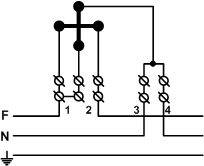
Fig. 1 Scheme for connecting a single-phase meter.
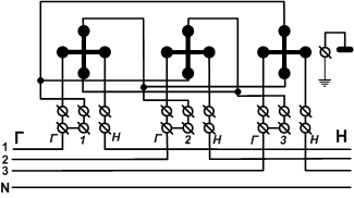
Fig. 2 Scheme of direct connection of CP4-И679 type meters with rated currents of 20 A and more to a three-wire and four-wire network.
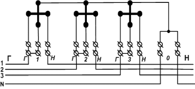
Fig. 3 Scheme of direct connection of meters type CP4-I678 with rated currents of 20 A and more in a three-wire and four-wire network.
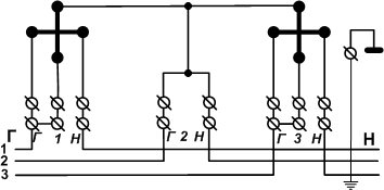
Fig. 4 Direct connection scheme of meters type CA3-I677 with rated currents of 20 A more than a three-wire network.
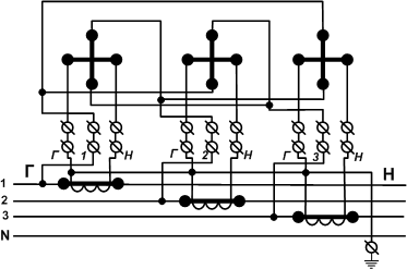
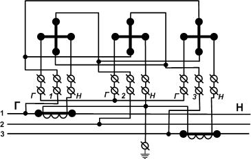
Fig. 5 Scheme of connection of the CP4U-I673M and CP4U-I679 type meters with rated currents of 1, 5A through any current transformers to a four-wire and three-wire network.
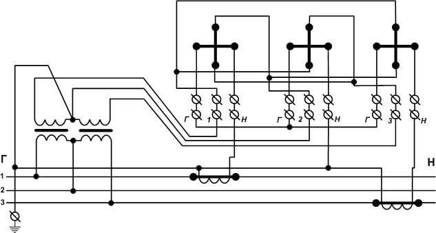
Fig. 6 Wiring diagram of the CP4U-I673M and CP4U-I679 type meters with rated currents 1, 5A through any current and voltage transformers in a three-wire network.
It should be noted that inductive counters rotate their disk most quickly with the correct connection. Counters (especially when using current and voltage transformers) have many more reasons to spin more slowly than they should:
- The current transformers can be confused (instead of 3 pieces 300/5 there are 2 pieces 300/5 and one 600/5). However, a transformer with a smaller coefficient can be supplied, and then the counter will spin faster (although in this case the probability that this current transformer will be burned from overloading increases), moreover, it is very easy to mix up - especially on older plates such incoherent that even on the removed transformer under A lamp and a magnifying glass does not always manage to see what is written on them. And in the electric shield, somewhere below this is completely unrealistic. We have to carry a whole heap of instruments.
- The beginning and the end of one of the current transformers can be confused, then 2 phases will be propelled forward, and one back (although in the end the counter will be propelled forward, albeit less than it should)
- The phases on the counter can be confused. That is, a current transformer from phase A is connected to the counter at input 1, and the voltage comes from phase B. It is usually easy to detect - the counter is rewound.
- Possible non-contact or breakage of one of the current transformers. Then the load of one of the phases will not be taken into account.
And if a little distraction, then sort out the bale of wires, especially when the panel is 3-4 meters is not always easy, even an experienced electrician-rleyleyschiku. In this sense, electronic is good because if something is not connected properly, they immediately swear (that is, they give an error message), but they are still expensive even for industrial enterprises.


Comments
Commenting on, remember that the content and tone of your message can hurt the feelings of real people, show respect and tolerance to your interlocutors even if you do not share their opinion, your behavior in the conditions of freedom of expression and anonymity provided by the Internet, changes Not only virtual, but also the real world. All comments are hidden from the index, spam is controlled.