§ 14 Principle of operation of the electronic meter A100
The design and operation of the main elements
Electronic counter module
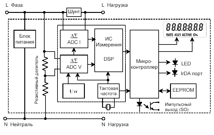
The high accuracy of active energy measurements is achieved using a special measuring IC including delta-sigma converters for current and voltage input signals, with a highly stable reference voltage and a crystal oscillator, and a digital signal processor (DSP). The output signals of two "delta-sigma" converters are sent to a digital signal processor (DSP), where they are processed and multiplied. As a result, the output of the digital signal processor (DSP) generates pulses with a frequency proportional to the power consumed. Also, the digital signal processor controls the extraction and filtering process of a possible constant component of the current and voltage signals. Counting pulses issued by a digital signal processor produces a microcontroller with a subsequent increase in the register of the active tariff and data storage in the non-volatile EEPROM memory. The microcontroller is an important link between the microprocessor and the peripheral devices of the circuit, controlling the operation of the liquid crystal display (LCD), the LED indicator LED, the IrDA port and the pulse output.
Constant calibrations used for necessary calculations Are loaded into the meter at the factory and stored in a non-volatile EEPROM memory along with the configuration.
The current circuit of the meter uses a low-resistance shunt with No more than 0.6 mOhm. Voltage before entering the "delta-sigma" entrance Converter passes through a series of highly linear resistive Voltage dividers.
All the main electronic elements of the meter are located on one Printed circuit board with planar-surface and through installation. On The following components are installed on the printed circuit board:
Measuring IC (measuring chip)
Microcontroller
EEPROM memory
Resistive voltage dividers
"Delta-sigma" current and voltage converters (ADC)
Power Supply
IrDA port
Liquid crystal display (LCD)
Quartz oscillator (megahertz range)
LED indicator light

Fig. 1. Structural diagram of the counter type A100
Power Supply
In all modifications of the A100 meters, a power supply is installed, Designed for a wide range of input voltage supply Network - from 184 to 276 V. For reliable protection against overload and fast Transient bursts, the input circuits of the power supply have A nonlinear suppression device, a series of current-limiting protective resistors And voltage, as well as the HF filter.
Voltage measuring sensors
To obtain a high-voltage signal and minimize the phase shift in a wide dynamic range, resistive voltage dividers are used.
Highly stable SMT resistors with a minimum temperature coefficient are used as dividers.
The voltage is applied directly to the main board, where, using resistive dividers, they are led to the required level of input signals for the delta-sigma of the measuring transducer (A / D converter).
The measuring IC in the circuit provides an accurate measurement of voltage and current for use in calculating the required quantities.
Conversion and calculation of signals
The measuring IC contains "delta-sigma" converters (ADCs) Which convert the voltage and current input signals to digital Code and digital signal processor (DSP), the corresponding Thus multiplying the results of the ADC. Then the measuring IC Converts energy into pulses for a microcontroller counter, Which processes the input pulses and transmits the data to the memory Counter, and if necessary, provides data transfer On the LCD and peripheral devices of the circuit (relays, ports). Also The measuring IC comprises a circuit for detecting power interruptions, Which sends the corresponding signal to the microcontroller. Constant calibrations stored in the EEPROM memory are loaded In the meter at the factory and become part of the corresponding operations Calculation of the desired values.
Microcontroller
The microcontroller performs various functions, such as:
Reception of control signals of the tariff input
Communication between DSP and EEPROM memory
Data transfer via IrDA port
Control LED indicator and pulse Output (S0)
Control of the liquid crystal display (LCD)
The microcontroller and the measuring IC constantly communicate For continuous processing of the input signals of the currents and Stresses. When the counter power is detected, The microcontroller initiates a shutdown and stores the calculated and Other data.
EEPROM memory
The A100 counters use non-volatile EEPROM memory
For long-term storage configuration, factory permanent
(Constants), calculated (commercial) and other data.
When
Restore (supply) power all data is read from memory
Microcontroller and the meter returns to the operating state before
power outages.
In the absence of power, the memory can maintain safety
Data not less than 10 years.
Liquid crystal display (LCD )
A liquid crystal display (LCD) is used for
Display of measured (calculated) data and status
Information.
Displayed LCD segments have high contrast and
Are easily distinguishable from different angles of view.
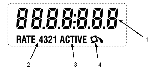
LCD can be conditionally divided into several information zones
(Fields), each of which displays certain information,
As shown in Fig. 1-5.

Auxiliary (service) functions
Additional functions
Additional (service) functions can be used for Obtaining background information on the reliability of work and accounting Active electric energy meter A100. These data may Be read on the PC via the IrDA counter port.Below we consider data giving information on reliable Accounting for electrical energy.
The flow of energy in the opposite direction
Number of reversals of energy
The A100 counter detects and writes to memory the total number Cases of energy flow in the opposite direction. Counter It detects a flow in the opposite direction only in the case of Exceeding the established energy threshold (5Wh). Threshold value Is installed in the factory.Total active energy released
The A100 counter detects and writes a total of
The value of the active energy given out.
Indicator of the reverse energy flow
The indicator of the reverse energy flow is displayed on the LCD in the case of
Detection of current flow in the reverse direction (output).
The indicator of the reverse energy flow will remain on the LCD until
Even when the current is again
Flow in the direct direction (consumption).
Counter operation time
The counter counts and registers in the memory of each complete Hours (without taking into account the time of lack of nutrition) and stores Duration of work for the period of 27 years.
Number of power outages
The counter counts and registers in the memory quantities Power outages.
The duration of the no-current mode
The time counter counts and records each complete Hour of the meter in the absence of current mode. This mode Allows you to detect an incorrect load pattern of the consumer.
Control functions
Counter of internal failuresThis device registers quantity in memory If the CPU is restarted due to an emergency Work (malfunction of the microprocessor's proper operation).


Comments
When commenting on, remember that the content and tone of your message can hurt the feelings of real people, show respect and tolerance to your interlocutors even if you do not share their opinion, your behavior in the conditions of freedom of expression and anonymity provided by the Internet, changes Not only virtual, but also the real world. All comments are hidden from the index, spam is controlled.