§ 15 Life and Death of a method number 13. (rollback generator)
Ghost haunting freebies on the internet! Method number 13, also known under the names of "generator rollback", "reactive power generator (?!)" "Heated", and the like. A distinctive feature is the stop mode (rollback) of electricity is that it does not require changes to the wiring circuits, grounding and general interference in the existing power circuit. It focuses hectares that operates on electronic meters has always been done. Usually this circuit is called - ". Method number __ E". Over the legendary and discussed in the network method rollback meters even difficult to come up. He kind of communism - it seems that's a little bit more, and here it is happiness. Detailed information (circuit and microcontroller firmware) is $ 11 (although some irresponsible person selling it for $ 2), but I found it online and free of charge. But do not run for your electronic and cash and grasping for soldering.
Driving theory and implementation.Let's take a look at the content of the sent description, the original description text in italics, my comments I will be bold.
The theory and operation of the scheme: In the first quarter period of the mains voltage of the power consumed by the network ie, charging capacitor C1, but charged through the transistor keys A and D, which are operated by high-frequency pulses of energy that is consumed on a charge of high frequency pulses.
We know that the counters including
e, as
it comprises an induction current sensor with a magnetic core which has a limited conductivity frequency (here about electronic let not agree - as a shunt for current measurement can be used by low-ohmic resistance, which has limited conductivity at a frequency can not be, in principle, but can be used, and coil. but with a very small inductive reactance, so that the error introduced by it is very low.
For a more complete explanation of an excerpt from the standard factory instructions for the electronic meter:
"Analog signals recorded with a precision current transformer, in which no iron core, and a resistive voltage divider fed to the microcontroller inputs.
The microcontroller converts the analog signals to digital, and multiplies them to calculate each second average power P (t).
Energy consumption is determined by integrating P (t).
"
Meters electronic single-phase active energy GEM Instructions
For the electronic counter magnetic field generated by the coil current brand does not matter.
There is probably not limited conductivity in frequency, and the sampling frequency of the electronic counter.
That is, if the electronic counter measures the current with a frequency of 100 times per second, and if the load will be consumed at a frequency of 200 times per second, then theoretically every second pulse is unaccounted for and the energy will be counted only half.
And now again look at the instructions in the factory:
2. Technical characteristics of the electronic meter GEM.
| Accuracy class | 1.0 or 2.0 (GOST 30207) |
| Rated voltage, Un | 100V; 120V; 127V; 220; 230 |
| Nominal (maximum) current Ir | 10 (60) A - kl.1.0; 10 (100) A - kl.2.0 |
| rated frequency | 50 Hz or 60 Hz |
| Sensitivity | 0,004In |
| Operating temperature range | from -20 0C to +55 0C |
| The power consumed by voltage circuit | <0,75Vt; <1VA |
| The power consumed by current circuit | <0.05 VA |
| meter constant | 4000 or 2000 pulses / kWh |
| Max. the number of tariff zones | 1 or 2 |
Counter sampling frequency (clock speed) at a frequency of 60 Hz should be at least 120 Hz (this is one of the theories of higher mathematics, the name I do not remember, but I do know that the sampling frequency should be double for accurate analog signal playback), but rather it is even higher and the load should be consumed with a frequency of 240 Hz, and it must be synchronized with an internal frequency counter that not practicable.) and induction, as
contain in addition to magnetic and even the mechanical part of the measuring system, have a very large negative error in the flow of high-frequency current.
(here, to some extent we can agree, really induction meter comprises an inertial aluminum disk. But there is another point. In order to save at least can be measured, the frequency should be sufficiently high. This will strongly litter household electrical harmonics network (frequencies different from the frequency of the network), it will endanger the other devices are not designed to work with high frequencies (different from the frequency of 50 Hz). And the impulses arising in the network will be very powerful (otherwise there will be the effect of underestimation). Certainly as a rule at the input of household devices typically cost filters, but they just are not designed to filter to 1.5-2 W currents. Therefore, these filters are surely fly, and behind them, and the devices themselves. and what do we have? we save 10 bucks on electricity and the burning TV 100, where it is likely, along with a neighbor (the public network). the question is, do we need such savings? While of course you decide. And running a little ahead.
Apartment wiring also has some some capacity, and immediately the question arises - if the frequency is high enough, and it should be that way, it does not smooth out whether all of these high-frequency pulses of the wiring capacitance.
As a result, it may be that for a series of high-frequency capacitor openings keys simply will not charge, and he will have nothing to give to the network.) Remains in the second quarter of the period, discharge the capacitor without any pulses network through the same keys.
Similarly, the second half-cycle through the other shoulder keys C and B. I wonder why everything is so difficult?
So, for example: need 2 kW, the counter has considered 0.5W, gave ideally 2 kW, the counter has considered -2 kW.
The result of the period - the induction meter spinning backwards at a rate of -1.5 kW and electronic worth up to 1.5 kW Where did these figures - will leave on conscience of the author, but even when workloads they will definitely be a lot less.
So already at the stage of theoretical analysis, we found that it's all electronic meters will not work, it is necessary to find out how the scheme is efficient for induction.
Although their krutnut ago, there are a million ways a much easier and more efficient.
Fig.
Figure 1 signals.
Appointment of circuit elements:
VD1-4, DA-1 in Figure 2. The power of the chip.
VD5,6, R5,6,7 in Figure 2. The pulse generator synchronized 50 Hz.
VD 2, R 5 in Figure 3. The rectifier module power supply.
VD3, C1 in Figure 3 stabilizer.
VT1 in Figure 3, a key element.
The pulse frequency f = 1.0 ... 3.0 kHz.
VHS 3-4 output pulse shaper.
General scheme: Fig.
2.
Details: VD1-4 - KC diode assembly 402B;
VD5, VD6- D226.
Or analogues 1N4007
S1-20..40mkf x 400 (can be used as the electrolyte and the electrolyte does not)
C2 S3-47mkf 12c;
S4-22rF.
DA1-78LO5 KREN5A or (5c) or LM7805.
VT1, VT2-KT315.
R1, R2, R3, R4-1.1kom;
R5-1kom.
All 0.5vatt
Tr-p 1-220v, III-7c, II-12c.
low-power
Quartz - 4MHz.
Modules A, B, C, D are identical and are collected as follows:
Fig. 3.
Details: VD1-D243, VD2 - D226; VD3-KS156A.
S1-20mkf. 12c
DA1 - PC120 (optocoupler).
VT1- KT809 (400V, 3A) on the radiator (all together) 100h150h50mm
VT2- KT315
R1-10kom, 0.5vatt
R2-5.1 ohms (approximately 10vatt wattage)
R3, R4, -30kom; R5-20kom, R6-1.1kom. 0.5vatt
The remaining resistance 1W.
I wonder how to behave transistor VT1 when submitting its collector emitter voltage relatively negative, even more interesting as it all reacts VT2?
Did he become a jumper?
And still wondering why in the chain R1VD1 a solid resistor?
Is this chain of something can save?
D1 is a simple chip microcontroller, which operates according to the program recorded in its memory (in accordance with the schedule of switching keys Fig. 1) Programming is done through connector X1.
Firmware is set to 2 kHz pulses and duty cycle of 50 \ 50.
These parameters can be changed before compilation.
To program copy in a notebook and save it with the extension .HEX
I did not cause the firmware and source code so that the scheme is still inefficient, but if people will ask, then lay out and them.
In the absence of the programming, or the controller, a control circuit may be collected by other principles, including logic elements.
Power rollback, if C1 = 20mkf is about 1 kW.
Interestingly, on a formula calculated the energy of the capacitor, but oh well, more on that later.
By increasing capacity and increasing power, but we need other transistors VT1.
Do not forget fuses.
When setting up better to use C1 = 5mkf without electrolyte.
Yes, the author poskromnichal generally electrolytes certainly cheaper and smaller, but they will not stand for a long time constant of the charge-discharge is small and WHAM.
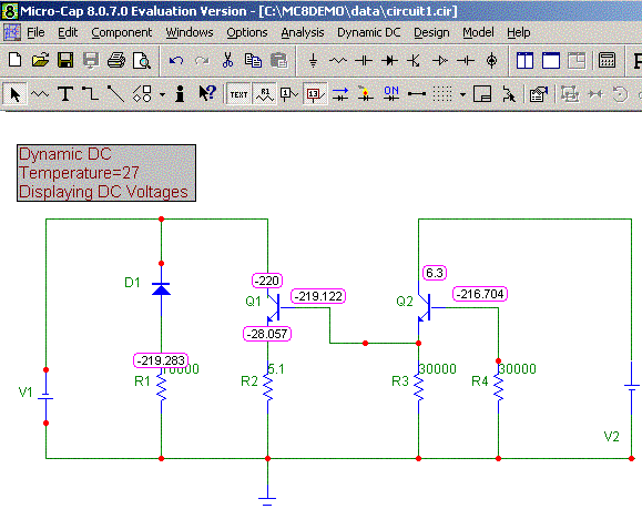
It so happened that my questions did not respond nor any megafaza positron, and the search for like-minded people on the forum and in a book megafazy positron complaints have led to the fact that my IP was blocked. So I decided to break the task into smaller pieces and simulate circuits in Micro-Cap. Look at the picture, I am extremely simplified circuit (zener kicked and added a second power supply, as the optocoupler is closed, it is also not painted), and now even the naked eye can see that during the negative half-wave transistor VT2 comes skiff. Why so it goes? Yes, everything is very simple - when applying a negative potential to the transistor collector junction K-B acts as a diode, but with a cathode collector.
(Note elremont. To confirm that this is all true, an excerpt of the forums in which the issue was discussed. Forum Addresses do not write, I think it's not so fundamentally.
| ||
|
| ||
|
| ||
|
Since the author has not contacted, but did not trust them I have no reason.)
But as it turned out it's just flowers ... Let's look at the current in the circuit currents. When charging the capacitor in the first quarter of the period, current flows in the following circuits: 1 D key contact on pin 2 D key, and then through the capacitor to the contact 2 and the key, and finally on track 1 of the key A. Is not it strange? Apparently conceived as a positron (megafazy) current must change its direction after the condenser or the keys are equally good conduct current in both directions.
See Figure 5, it does not remind you of anything? But not guessed, this is a single-phase voltage of the inverter circuit (called an inverter voltage converter DC electrical power to AC). Guess how to contact connects a current source (condenser). Again, do not guess, the current source is connected to the terminals AB and CD with terminals remove the break ... continue?
Many people ask the question of whether the correct operating principle - indeed induction meters have a large negative error in the RF load, but otherwise the principle is wrong. With electronic counters this trick does not pass (maybe I just have not happened).
Again elremont:
And now an excerpt from the forum where this issue discussed electricians professionals:
-viktor-
№13 method works, even though I have not tried it.
There are a few downsides - quickly burn out the transistors and the network goes fairly strong interference !, so badly shows telly (our neighbors too).
The neighbors will find out what is going on
-evroelektrik-
Hello colleagues!
Who will expose!
METHOD 13 Positron is not working and can not work in principle!
For 2 months, we bought this method (11 bucks - a penny), to obtain the following results: the diagram there is correct, the firmware chips, too, on the oscilloscope can see that everything is fine.
BUT!!!
Any attempt to connect to a network ready device is failing.
Just burn the power transistor.
It was tried out all: interchanged modules changed the ratings detail, modified device, but the same result.
In addition, there are experts in this issue (not CIS), which explained why it would not work.
In addition, if someone fail to collect this method will keep such interference that the use of an apartment block in the network becomes impossible.
I have a different scheme that really will work, but the cost of its components comes to $ 500.
Except for sale, collect it unprofitable.
RESULT: Positron - freeloader, sells untested schemes.
QUESTION: There is a blochok size of charging for mobile phone, slows or completely stops the counter when you turn into a power outlet (single-phase), while in the counter should be set to small invisible bug.
We have a real blochok, we have a scheme of the bug.
Somebody knows?
OFFER: anyone interested, send FREE All pozitronovskuyu chart of a method 13. Waiting in exchange for any information on the theft.
On this subject we can talk in person, write me at [email protected] .and for general guidance at the same time try to open a new topic.
Write!
-Den-
Now I was led to the idea of №13 lohovodov positron http://antipozitron.best-host.ru/ etc.
No, I have not bought the circuit, I have developed their own, on the other microprocessor, on the other keys.
Sam wrote softinkoy implements the principle scheme debugged components picked up, the scheme works, diagrams of signals on an oscilloscope checked, everything is OK - the capacitors are charged, the keys when it is necessary to open, only one problem - BACK COUNTER not cool, not even the course of brakes!
I tried to change frequency 2 to 10 kHz, all by double-checking, it works, spent a lot of time developing the scheme, the development of the algorithm of "machine", the time for writing and debugging programs, during the assembly solder and debug circuit, does not work no words ... ... Cool as twisted, it does not even slow down, there is no it at all ....
It's all about the physics of the processes.
Little hope is that I have some artful meter: with ECHO-197 (Kharkov) What I doubt very much ((((((((I sit looking at this thing - like the old lady with nothing ..... Show me happy owner of a working method of number 13, I give the money for it ... Can I also sell 100% "working" scheme for 1000 $ [email protected]
-eksperementator-
and I once seduced by the idea.
also sat as an "old woman with nothing," it all depends on how to treat this faktu- ever forget how annoying curiosity, piggy-or as the completion of invaluable experience - and join the ranks of "broken" -this each of which, as we know, the two "unbeaten" give
-A guest-
On the way №13.
It's like another attempt to create a perpetual motion machine, which is created out of nothing for something.
To test this method of implementing the scheme it was collected, and found that this method does not work.
Disc counter just standing still.
And when you connect to other users begins to rotate, where it should be - GO, as if nothing had happened.
The fact that the network of energy in the first half of half-cycle of the capacitor becomes charged, and the second is returned to the network (except for some losses).
And it does not depend on the pulses to charge the capacitor or continuously for half a halftime.
Let me explain this with a simple example.
If we scoop from the well bucket of water, and Spill it back, what will change?
Nothing.
Now, if we draw water into the bucket portions (pulse mode capacity charge) and also Spill it back?
We will spend their forces only to lift water from the well and pouring it back.
In the case of the scheme - is to buy parts of its assembly.
And a waste of money for the purchase of the scheme, which is the use of no.
Although, if to collect and organize, experience in electrical engineering and electronics, you will surely gain.
If you are interested, please contact [email protected] send for a modest fee.
-endryu-
it's all right.
pull the network energy, then we return it back in the same amount.
that is, minus the loss processes, heating and so on. But !!!!!!
the idea is to meter error at a high frequency !!!!!
I personally think that the air-conditioner, which is charged, and smoothes our RF pulses.
he is not charged from 0 V at each pulse, and the charge from the previous point.
-eksperementator-
in general, the idea of the error counter on the "high" frequency seems to me patently false - especially let loose "the masses" to slip off track - it could not have the idea of "electronic" Unreelers born out of nowhere (no smoke without fire does not happen).
I think the essence of the following - it is known that by passing a direct current through the current coil counter it "lies" -sut that the magnetic flux changes in the core of the coil current is not zero sine wave and a little later (depending on the VDC. ).
Our goal is to "magnetize" the core of the coil current.
as?
1.-connect to it and after -not battery suitable - it is necessary to climb to the counter.
2.-magnetize is no current in the network - this is regularity to 100 times per second.
at zero in sinusoidal have tsep- phase in the outlet -m Lateral katushka- automatic -UZO -... secondary winding of the power transformer -... UZO- avtomat- zero in rozetke- in the amount of chain without tension with resistance in several Om-- this time in the discharge outlet Conder (300 10000mKf) through 100 A klyuchi- core
current coil "fly" in saturation and will become a permanent magnet - and the flow of current in the future through this coil a magnetic field changes the core will not further our recharge partially discharged Conder s get down to the negative half-wave sine wave.
this is only a theory, born when placing the circuit in 100A-keys
a guest
Counter actually has a negative error at high frequency.
If the counter is included under the standard scheme, connect it to the LF generator and increase the frequency of 50Hz, then with increasing frequency drive slow speed and at 560 ... 600 Hz stops (type of counter-CO 2, the frequency may be different for other types).
The tension was sinusoidal and rectangular, with no DC component.
In both cases the effect is the same.
Switching charge (charge current termination) by itself does nothing.
The average value of the current through the capacitor is obtained is the same as without pulses.
And not only depends on the frequency.
This is verified.
In general, if the capacitor is charged from a separate source and discharged into the network, the counter begins to turn back.
But where to take this a single source, and is not it better just to feed the load from him, because
he must develop the same power, which we want to unwind.
At the same time we are a source of food and for the neighbors.
The idea of a magnetic bias is likely to work, but from a single source: the battery, for example.
To charge Conder 10000mkF to 300V in less than a quarter of the period required substantial power.
a guest
Working scheme even if there is, then it is likely to work with a separate power source.
Its thickness should be not a big msovsem.
To counter unwound at a rate of 2 kW / h is necessary through 9A skip current winding current, voltage with her just 2.7V.
Power in this case is 24W, and if the wind off 1kW / hour, only 6 watts.
The challenge is how to transfer it to the current winding through the network, which has a voltage of 220V.
These are the pies ... If after you have read the above, you have a itch to spend 11 bucks, buy the best books on electrical engineering.
Uses will be more accurate.

Comments
Commenting, keep in mind that the content and the tone of your messages can hurt the feelings of real people, show respect and tolerance to his interlocutors, even if you do not share their opinion, your behavior in terms of freedom of speech and anonymity offered by the Internet, is changing not only virtual, but real world. All comments are hidden from the index, spam control.