INFLUENCE OF THE ERROR OF TRANSFORMERS
The decline in production in recent years has led to a reduction in loads in a number of power system nodes, as well as a reduction in consumption by the industry, which in turn has caused a negative error in automated systems for monitoring and accounting for electricity (ASKUE). The reason for this was the emergence of a negative error in the primary current and voltage sensors, which use current and voltage transformers. This paper is devoted to the investigation of the causes of errors and ways of eliminating the undercount of power consumption in AMR systems.
The errors of current transformers (current and angular) are due to the presence of a magnetizing current and are calculated by the formulas [1, 2]:
Current error
 (1)
(1)
Where lm is the average length of the magnetic flux in the magnetic circuit, m;
Z2 - resistance of the secondary current branch (impedance of the secondary circuit and secondary winding), Ohm;
F - frequency of alternating current, Hz;
Sm is the actual section of the magnetic circuit, m2;
J is the loss angle, and a is the angle of phase shift between the secondary emf.
E2 and secondary current I2, degrees;
Angular error
 (2)
(2)
The main influence on the errors of current transformers is provided by their current loading and resistance value of the secondary circuit. In conditions of a reduction in electricity consumption by industrial enterprises, the load of current transformers often does not exceed 5-15%, which leads to a significant increase in errors.
The limiting values of the current and angular errors of current transformers for measurements (according to GOST 7746-89) are given in the table.
Accuracy class |
Primary current,% of nominal |
Marginal error |
Secondary load,% nominal, at cos j 2= 0,8 |
||
Current |
Angle |
||||
Mines |
Hailstones |
||||
0.2 |
5
|
± 0.75
|
± 30
|
± 0.9
|
|
0.5 |
5
|
± 1.5
|
± 90
|
± 2.5
|
25-100 |
The results of calculating the angular and current errors of current transformers of the type ТПОЛ 600/5, accuracy class 0.5, produced by formulas (1) and (2), are shown in Fig. 1 and 2 (a thin line is a calculated curve, a thick line is an approximation). The form of the approximating expression and the criterion for the agreement of the calculated and approximating curves are shown in the figures.
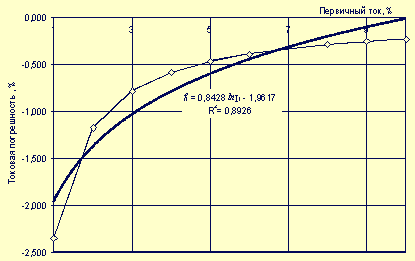
Fig.
1
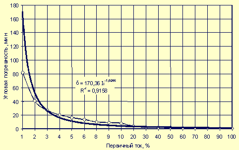
Fig.
2
For the ranges of variation (1-10% and 10-100%) of the primary current from the nominal value, the mathematical models of the current error of the most common current transformers are:
ТПОЛ10- 600/5
Df [%] = 0.8428 * ln I1 - 1.9617 for 1 <I1 <10%
Df [%] = 0.0841 * ln I1 - 0.3919 for 10 <I1 <100%
TLSH10- 2000/5
Df [%] = 0.7227 * ln I1 - 1.6815 for 1 <I1 <10%
Df [%] = 0.0722 * ln I1 - 0.3353 for 10 <I1 <100%
TPShFD10- 3000/5
Df [%] = 0.5986 * ln I1 - 1.2261 for 1 <I1 <10%
Df [%] = 0.0597 * ln I1 - 0.1111 for 10 <I1 <100%
The values of the primary current I1 of the current transformer in the formulas should be substituted as a percentage of the nominal value.
Investigations of the errors of current transformers carried out at NICE, showed acceptable convergence of theoretical and experimental results. In Fig. 3 shows the results of an experimental study of TT type TPLM10-200 / 5, accuracy class 0.5.
The results of the study of current errors of various types of current transformers with a primary rated current of 75 - 600 A made it possible to draw the following conclusions:
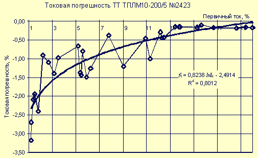
Fig.
3
- In the range of variation of the primary current from the nominal value of 1 to 25%, the current error has a negative sign;
- With an increase in the primary current, the absolute value of the current error decreases;
- Experimental studies confirm the correctness of the mathematical model of the current transformer current error;
- The current error of the current transformer in the automated metering system will allow to reduce the unbalance in the substations;
- The amount of electricity supplied to consumers due to the negative current error of current transformers is underestimated compared to the actual value; Therefore, the current error of the current transformer in the automated metering system will allow to more accurately estimate the amount of electricity supplied to consumers and obtain a certain economic effect, which will be evaluated further.
The second source of measurement error is the voltage transformer.
According to [3, 4], the voltage error is determined as follows: DU = DUn + DUx (3)
Where DUн is the voltage error caused by the load current,%;
DUx - voltage error due to no-load current,%.
Using a vector diagram, we can express with sufficient accuracy the components of the voltage transformer error as follows:
![]()
![]()
Where U2 is the voltage of the secondary winding of the transformer, V;
Ia- the active component of the no-load current, applied to the secondary winding of the transformer, A;
R'1 - reduced resistance of the primary winding of the transformer, reduced to the secondary winding, Ohm;
I'p - reduced reactive component of the no-load current, applied to the secondary winding of the transformer, A;
X'1 - reactance of the primary winding of the transformer, reduced to the secondary winding, Ohm;
I2 - load current of the transformer, A;
R2 - resistance of the secondary winding of the transformer, Ohm;
Cosj2 - load power factor, rel.
Units;
X is the inductive resistance of the transformer, Ohm.
The angular error of the voltage transformer is defined as
![]() ,
,
Where d'x is the angular error due to the idle current;
D'n is the angular error due to the load current.
The components of the angular error are defined as
![]() ;
;
![]()
The results of calculating the errors of the voltage transformer are shown in Fig. 4 and 5. The main influence on the error of the voltage transformer is the value of the secondary load I2.
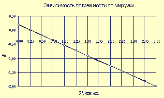
Fig.
4
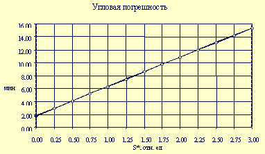
Fig.
5
The dependence of the voltage transformer error on the load factor on power (the ratio of the actual load of the secondary winding of the voltage transformer to the nominal value of the load) has the form
DU [%] = - 0.73 * Ks + 0.35,
Where K3 is the load of the voltage transformer in the secondary winding, rel.
Units
The resulting expressions for the errors of current transformers and voltage transformers make it possible to increase the accuracy of electricity metering at substations.
The effectiveness of the introduction of AMR in the substation depends
- From the costs of introducing AMR;
- From the economic effect resulting from the implementation.
At present, the account of the released electricity and the calculation of the energy balance at most substations is conducted with the help of electromagnetic counters without taking into account the errors of current transformers and voltage transformers.
Often, the voltage transformers work when the secondary winding is loaded, exceeding the nominal one by several times, i.e. with a negative error. Most of the load of the voltage transformer is made up of measuring devices connected to them, in particular electromagnetic energy meters. For example, in the substation "Sverdlovskaya" induction meters SAZU-I670M, power consumption of 4 watts are installed. As a result of the introduction of automated metering systems, induction meters will be replaced by electronic meters, such as PSCs, the power consumption of which is two times less than 2 watts.
In this case, the load factor of the voltage transformer is reduced by half to a value of 1.1 and, consequently, the error of the voltage transformer is reduced from 1.15% to 0.5%. Reducing the error of the voltage transformer will lead to an increase in the accuracy of accounting for the electricity supplied to consumers.
Accounting for current errors in current and voltage transformers in the AMR system gives an economic effect. To assess the economic effect of the introduction of AMRMS, an estimate was made for the annual electricity consumption at the substation "Sverdlovskaya", taking into account the errors of the current and voltage transformers. The calculation was made as follows:
- According to the available data, hourly values of active power (taking into account the errors of current and voltage transformers) by input and outgoing lines were calculated for the characteristic winter and summer days of the year (1997 and 1998) according to the formula
Pfact = P * KI * KU,
Where P - the average hourly power values, determined by the meter readings;
KI is a coefficient that takes into account the current transformer current error, KU is a coefficient that takes into account the error of the voltage transformer.KI = 1 - (Df I/ 100), KU = 1 - (Df U/ 100),
Where Df I- the current transformer current error, Df U- the error of the voltage transformer. - The consumption of electricity for typical winter and summer days was determined taking into account the errors of the current and voltage transformers (W.fact and W. fact) and without taking into account the errors (W and W) for inputs and outgoing lines:
W.fact = S Pact.s,
W. Fact = S Pact. L,
W3 = S P3,
Wl = S Rl. - The amount of annual consumption of active electricity by inputs and outgoing lines was calculated from formulas
W. fact = W. fact * Ns + W. fact * Nl,
Wz = W3 * N3 + Wn * Nl,
Where N3 = 213 and N5 = 152 - the number of winter and summer days per year. - The effect from the introduction of AMR is determined by the formula DW = SW.fact - SWg,
Where SWг.факт and SWг - annual consumption of electricity by outgoing feeders with and without taking into account the errors of current and voltage transformers, respectively.
We will estimate the economic effect for two options.
- When taking into account ASKUE current errors of current transformers and reducing the errors of voltage transformers due to reduced power consumption of electronic meters, the effect will be:
According to 1997 data.
DW = 331021094-326683013 = 4338081 kWh / year;According to the data for 1998.
DW = 294647641-290512594 = 4135047 kWh / year.In monetary terms, the economic effect (E) is equal (at an electricity price of 0.4 rubles / kWh)
E = 1735 ... 1650 thousand rubles per year. - Taking into account only the reduction in the errors of voltage transformers due to the reduced energy consumption of electronic meters, the effect will be:
According to 1997 data.
DW = 328316428-326683013 = 1633415 kWh / h;According to the data for 1998.
DW = 292196976-290512594 = 1684382 kWh / h.In monetary terms, the economic effect is equal (at an electricity price of 0.4 rubles / kWh)
E = 653 ... 674 thousand rubles per year.
In conclusion, the following conclusions can be drawn:
- Reduction of loads in a number of nodes of the power system, as well as reduction of electricity consumption by industry, led to a negative error in current transformers and, accordingly, to commercial underestimation of the consumed energy;
- To eliminate the underestimation of electricity consumption, it is necessary to introduce correction factors;
- Taking into account the errors of current transformers in the ASKUE, as well as reducing the errors of the voltage transformer due to the introduction of new electronic meters, lead to a significant economic effect.


Comments
Commenting on, remember that the content and tone of your message can hurt the feelings of real people, show respect and tolerance to your interlocutors even if you do not share their opinion, your behavior in the conditions of freedom of expression and anonymity provided by the Internet, changes Not only virtual, but also the real world. All comments are hidden from the index, spam is controlled.