| section Home
Production, Amateur Radio amateur Model aircraft, rocket- Useful, entertaining |
Stealth master
Electronics Physics Technologies invention |
space Mystery
Earth Mysteries Secrets of the Ocean Stealth section Map |
  |
| Use of material is permitted for reference (for websites - hyperlinks) | |||
Navigation: => |
Home / Electronics / Circuits / Special devices ... / |
|
Assembling laser based organic dye
See also: |
The diluted organic dye solution is illuminated trigger homemade lamp. The laser emits a light beam diameter of 5 mm, which can be focused lens system. beam color depends on the type of dye, and intensity of the flash trigger amplifying tube length.
The tube amplifier - the basis of the laser. It is made of quartz glass, its diameter is 5 mm. The ends of the tube are closed by two flat windows made of quartz glass, and the tube itself is sandwiched between two mirrors. The second tube is the same - a trigger - is located parallel to the first. Both tubes are mounted in an elliptical reflective mirror tube (Fig. 1). Flash Trigger reflected by the elliptical mirror, focuses on amplifying tube, so that the amplifier and the trigger is located at the foci of the elliptical reflector. The flat reflecting mirror (10 mm diameter) coated with silver or aluminum. One of the mirrors reflects the light completely, and the other - a little more than half. That part of the light that passes through the second mirror, the laser beam is.
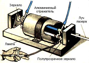
Fig. 1. General view of the laser.
(Reflector conventionally cut. Visible light and power.)
Displaying the connection of the vacuum pump to the lamp
The laser is triggered only by high power light flashes. How is this achieved? The quartz glass tube with stainless steel or copper electrodes and filled with air - that's the whole trigger. Electrodes are attached to the terminals of the capacitor capacity of 15 microfarads with a charge capacity of about 3 thousand. In. To start trigger is necessary to create a vacuum in it to 60 mm Hg. As soon as the pressure has fallen to the desired value, the capacitor is discharged and will flash the laser.
Before the next laser pulse power must be cooled to room temperature. To this dye solution continuously flows through the reinforcement tube. At the ends of the reinforcement tube don and paste glue BF-2 copper supply tube. Transparent quartz windows are glued to the ends of the copper tubes. dye solution flow rate should not be less than 4 l / h.
From the air evacuation from the trigger perfectly cope manual vacuum pump (or electric, if any). Pump outlet must be immersed in a jar with soapy water, preferably in the detergent solution. This is to ensure that the air in the room where the laser operates, not contaminated vapors oils. Any contamination of the alcohol solution of the dye will not allow to squeeze even a hint of a beam from a laser.
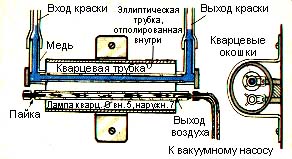
Fig. 2. Laser sectional.
Note the location of the lamp
and an amplifier at the foci of the elliptic reflector.
Runs a trigger like this: in a rubber tube that goes from the trigger bulb to the vacuum pump, cut into T-shaped glass or metal tube. When running a vacuum pump air will be pumped through the open end of the T-shaped tube. If the process tightly shut tee thumb, the pump will start to pump air from the trigger.
Lamp electrodes made of copper or stainless steel. The diameter of the inner part of about 8 mm, and the ends are rounded and polished as possible.
Lamp power and mounted exactly parallel at a distance of 15 mm from the base - plate of plastic or thick plywood. The distance between the lamp axis and the amplifier 12 mm.
The reflector is a thin-walled aluminum tube of 80 mm in length and 25 mm internal diameter. Inside the surface should be well polished. Then gently squeeze the tube should be in the grip so that it becomes elliptical in cross-section. A large axis of the ellipse shall be at least 3 mm longer small. Dimensions of these must be carefully corrected. The reflector is attached to the base metal clamp. A large axis of the ellipse is parallel to the ground plane. The foci of the ellipse (the distance between them is 12 mm) fixed trigger and amplifier (Fig. 2). The axes of the tubes must be strictly coincides with the focus of the elliptic reflector. Cells for fixing the flat reflecting mirrors and adjust their parallelism are shown in Fig. 3. Set screws with springs are used to adjust the beam angle of the meeting with a mirror. Half mirror silvered surface directed toward the reinforcement tube. It is made as a mirror. The glass plate is degreased thoroughly, cover with one hand and the nitro carried her silver mirror reaction known from the chemistry course. It is important to determine the retention time window in the reaction solution turned to a translucent layer of silver. This is achieved by a purely experimental 5 steklyshek maintained in a vessel with a solution of a different time.
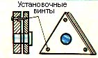
Fig. 3. Cell for fixing reflecting mirrors
and adjust their parallelism.
It is desirable that the mirror transmits about 18% of light. This can be verified using the light meter.
Trigger Power supply is mounted in a box under the ground, on which fixed elliptical reflector, trigger and amplifier. The wires from the capacitor to the trigger should be as short as possible and to have minimum resistance to reduce the duration of the discharge of the capacitor, since the intensity of the beam emitted by the laser depends on the duration of the flash. It is best to use copper bus-section 10x1 mm.
Driving power supply trigger (Fig. 4) is quite clear and will not cause difficulties when installing.
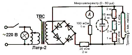
Fig. 4. Power supply.
more dyes may be used In a laser. For initial experiments is better to take rhodamine. This allows to obtain an orange dye laser beam from yellow-green to red. To prepare such a solution need to 1 liter of methyl alcohol is added 45 mg of rhodamine.
An interesting dye emitting a beam of intense blue color is diethylaminomethyl-coumarin. This paint must 75 mg per liter of methyl alcohol.
sodium fluorescein is used in a concentration of 45 mg per liter of ethanol.
Ready laser requires a single, but very responsible setting: it is necessary to establish a flat reflective mirror exactly perpendicular to the axis of the amplifier and strictly parallel to each other. Otherwise the laser will be dead. To install the mirrors need a flashlight, binoculars or a telescope, and the best school telescope. It is necessary to have two prisms and representing in cross section is an isosceles right triangle. Every binocular has four such prisms. On the glass lantern glued iris of an opaque material pinhole against filament light bulb filament. Semitransparent mirror is removed, and the devices are located, as shown in Fig. 5 above. Two incandescent filament bulb image appears in the telescope lens.
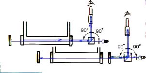
Fig. 5. Setting up the laser.
On the upper part of the figure semitransparent mirror is removed.
Produced position adjustment opaque mirror.
The bottom part of the figure shows the path of the system
when adjusting the position of the semitransparent mirror
Both images (prism refracted and reflected by the mirror opaque) must be aligned in such a way that the combined image is exactly in the middle of the field of view of binoculars, a telescope or a telescope. Then set a semitransparent mirror (Fig. 5 below) and double-filament image (reflected by a semitransparent mirror and a previously received registration) again combined. Thus it is necessary to regulate the installation of only a half-mirror. When all this is done, your laser is ready for operation.
Publication date 05.12.2003gg.
![]()

Comments
Commenting, keep in mind that the content and the tone of your messages can hurt the feelings of real people, show respect and tolerance to his interlocutors, even if you do not share their opinion, your behavior in terms of freedom of speech and anonymity offered by the Internet, is changing not only virtual, but real world. All comments are hidden from the index, spam control.