
|
Start of section
Production, amateur Radio amateurs Aircraft model, rocket-model Useful, entertaining |
Stealth Master
Electronics Physics Technologies Inventions |
Secrets of the cosmos
Secrets of the Earth Secrets of the Ocean Tricks Map of section |
  |
| Use of the site materials is allowed subject to the link (for websites - hyperlinks) | |||
Navigation: => |
Home / Electronics / Schemes / Power supply of equipment / |
|
STABILIZER WITH MICROCONTROLLER CONTROL
![]()
Godin Alexey Valerievich
Scheme, modes of operation of the device

The stabilizer operates according to the principle of step voltage correction performed by switching the winding taps of the autotransformer T2 using triac Q1 ... Q6 triacs under the control of a microcontroller ( MK ) monitoring the voltage level in the network. After switching on the QF1, the mains voltage is supplied to the transformer T1 and the microcontroller starts to operate according to the specified program.
The display lights up and after 3 seconds "PREPARATION FOR WORK" appears on the display ( figure 2 ). The next 7 seconds the microprocessor analyzes the mains voltage, and if it is within 120 ... 270V , depending on the measurement results, one of the triacs VS1 ... VS6 opens, thereby connecting one of the six branches of the autotransformer .
The load is connected to the fifth (bottom of the circuit) tap of the autotransformer through the circuit breaker QF1 , which serves to limit the power consumption. In this case, two "internal" voltmeters induce the active line voltage in the upper line of the LCD display, and the voltage on the load in the lower line ( Fig. 3 ).
If the voltage is below 120V or above 270V , the load is de-energized. At this time, the active line voltage is induced in the upper line, and the inscription "PROTECTION MODE" flashes in the bottom line ( Fig. 4 ).
|
|
|
Fig. 2 |
Fig. 3 |
Fig. 4 |
As soon as the voltage enters the range 120 ... 270V , the load will be reconnected.
In the event of a mains voltage failure and subsequent appearance, the microprocessor automatically reboots and after 10 seconds reconnects the load.
The galvanic isolation of triacs from MK is carried out by optocouplers U1 ... U6 . In the process of regulation, the opening pulse is removed from the triac on and applied to another triac at the time of the sinusoidal transition through "0" , thereby eliminating "current impacts" in the windings and triacs. This is achieved due to the fact that for 1 sinusoid period the microcontroller measures the state of the mains voltage amplitude 100 times! The oscillogram of this process is shown in Fig. 5 .
Fig. 5
For the correct operation of the circuit, it is necessary that the anodes of the triacs and the wires from the "internal voltmeters" be connected to the phase conductor.
Design and details
The stabilizer controller ( Figure 6 ) is assembled on a printed circuit board 10x12cm from a single-sided foil-coated fiberglass strip with a thickness of 1.5 mm ( Fig. 7 ). And a variant of a printed circuit board with two transformers TPG 2-12 on the board was developed.
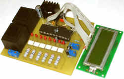
Fig. 6
Fig. 7
Alternatively, the HL1 ... HL8 LEDs can be mounted on the side of the printed conductors so that when the PCB is installed in the housing, they are inserted into 5 mm holes drilled in the front panel of the device.
The controller in this case is installed (print to the front panel) on racks of appropriate height, screwed to the front panel of the stabilizer housing with screws in the sweatbox.
The nominal value of the current-limiting resistor R22 must be selected so that the current flowing through the LEDs of the triacs of the triacs U1.1 ... U6.1 is within the range of 8 ... 10mA . In the diode bridge VD1 ... VD4 Schottky diodes 11DQ10 are used , due to the low voltage drop on them. Trimmer resistors R2, R10 wire multi- turn SP5-2 or SP5-3 . Constant resistors R1, R5 ... R9 it is desirable to use type C2-23 (metal-dielectric) c with a dissipation power not less than that indicated in the scheme. The rest can be of any type. Electrolytic capacitors C1, C2, C4, C5, C8, C9 can be any, with the capacitance indicated on the diagram, and voltage not lower for them specified. Condensers C3, C6, C7 - any film or ceramic. Capacitors C10 ... C15 - film for a voltage not lower than 630V .
Imported triac MOC3052 optocouplers (U1 ... U7) are selected because they do not contain built-in voltage transfer controllers through zero. This is not necessary, because Synchronization of switching off one powerful triac and switching on the other is done programmatically.
Powerful triacs VS1 ... VS6 - BTA 40-600 . All triac VS1 ... VS6 are installed on one heat sink, with a cooling surface area of at least 800 cm 2 , preferably using thermal paste to ensure reliable heat dissipation. The stabilizer chip ( DA1 ) KR1158EN5A (B) must be installed on the heat sink of at least 80 cm 2 .
The transformer T1 is self-made, designed for the overall power of 8W , which has a cross-sectional area of the magnetic circuit of 2.3 cm 2 . Its network winding I is designed for a maximum emergency voltage of 380 V , contains 8669 turns of PEV-2 wire with a diameter of 0.1 mm . Winding II contains 585 turns of PEV-2 wire with a diameter of 0.25 mm . At a nominal voltage of 220V, the output winding voltage should be 13.5V at a current of 250mA .
Customize
The device configuration is as follows. A reference voltmeter (digital tester) is connected to the network. The controller circuit is included in the network. Trimmer resistors R2 and R10 alternately set up both internal voltmeters of the stabilizer for the readings of the reference voltmeter. To calm the soul with the help of LATR, you can make sure of the successive switching of the LEDs HL2 ... HL7 at the threshold crossing 120, 137, 157, 179, 205, 235 and 270 V.
This completes the device setup.
Methods of tapping
There are two ways of switching off the taps of the autotransformer T2 .
FIRST METHOD.
Switching of bends "on the input" (
Fig.
8 ).
The triac keys are up to the autotransformer, switching the taps so that the load always removed from one tap ( No. 5 from below) is in the required range of the output voltage of 205 ... 235V .
Fig. 8
Advantages: when winding the autotransformer it is not necessary to take into account the overvoltage factor up to 380 V ( 380/220 = 1,7) , which affects both the dimensions of the core and the amount of copper needed for winding. And it is possible to use low-voltage triacs BTA40-600 , since triacs at exceeding 270V simply disconnect the autotransformer from the network.
Disadvantages: the current flowing through the triacs and the primary winding of the autotransformer is limited at the level of 25A , and as a consequence the current of the output winding is equal to 14.5A .
Conclusions : the switching option "on the input" allows to remove from the triac BTA40-600 3kW of useful power. There is savings on copper, core and triacs.
If you are satisfied with the power of the stabilizer 3kW , then this scheme is for you! In my estimation, it has more advantages than disadvantages!
METHOD OF SECOND. Switching of bends "on exit" ( Fig. 9 ).
Fig. 9
The mains voltage is connected to tap No. 2 . The triacs are placed after the autotransformer, connecting to the load that tap, where the voltage is within the required limits of 205 ... 235V .
Advantages: this version of the connection allows you to "remove" from the triac BTA 40-600 5.5 kW useful power, which is almost 2 times more switching option "on the input."
Disadvantages: the disadvantage is the need to use triacs designed for operating voltage not less than 800 V (in the three upper circuits according to the autotransformer tap scheme), and by 1.7 times the number of turns of the autotransformer winding.
Conclusions : in order to eliminate the above-mentioned drawbacks, it is necessary to introduce an additional powerful triac key to 80 A (TC142-80-8) directly in front of the autotransformer, which will disconnect the primary winding (branch No. 2 from below under the scheme) when the mains voltage exceeds 120 ° . .270B . In analog versions, this will lead to a significant complication of the controller circuit, therefore, a switching scheme "by input" is preferable. In the microcontroller version, this can be done by adding several lines in the microcontroller program!
The use of cheap triac BTA41
In the variant of commutation "on the input" the power in the load will be 1.2 kW . All triacs can be BTA41-600 . At the output of the autotransformer (before the load), it is necessary to put the QF2 automatic device on 6A , and use the 10A automatic machine as QF1 .
In the switching variant "on output" the power in the load will be 2.2 kW . To do this, the tri-top trimmings should use triac BTA41-800 .
This is necessary, because The voltage in these branches with an emergency voltage in the 380V network will exceed, or will be close to 600V . The remaining (lower) can be BTA41-600 . At the output of the autotransformer (before the load), it is necessary to put the QF2 automaton on 10A , and as QF1 to apply the automatic device to 20A .
It is tested, that through a triac BTA41 the maximum current up to 13А can proceed. When this value is used, the triac's leads are fused as fuses, since their cross-section is 0.6 mm 2 ( 0.6 x 1 mm ). Optimum limit current through triacs at the level of 10A .
Literature
Godin A. Voltage stabilizer of increased accuracy with a load power up to 6kW - Radio Amateurs, No. 7/2005 , p. 36-40 .
For all questions related to the described device, you can get advice by sending a request to the email address of the author indicated at the beginning of the article.
print version
Author: Godin Aleksey Valerevich, Moscow
PS The material is protected.
Date of publication 22.09.2006гг
![]()

Comments
Commenting on, remember that the content and tone of your message can hurt the feelings of real people, show respect and tolerance to your interlocutors even if you do not share their opinion, your behavior in the conditions of freedom of expression and anonymity provided by the Internet, changes Not only virtual, but also the real world. All comments are hidden from the index, spam is controlled.