
| Start of section
Production, amateur Radio amateurs Aircraft model, rocket-model Useful, entertaining |
Stealth Master
Electronics Physics Technologies Inventions |
Secrets of the cosmos
Secrets of the Earth Secrets of the Ocean Tricks Map of section |
  |
| Use of the site materials is allowed subject to the link (for websites - hyperlinks) | |||
Navigation: => |
Home / Electronics / Schemes / Power supply of equipment / |
|
SIMPLE TWO-STEP VOLTAGE TRANSFORMER
Author of the article: A. Chaplygin
A two-stroke pulse generator was assembled on transistors. The positive feedback current flows through the transformer windings 3 and 4 and the load.
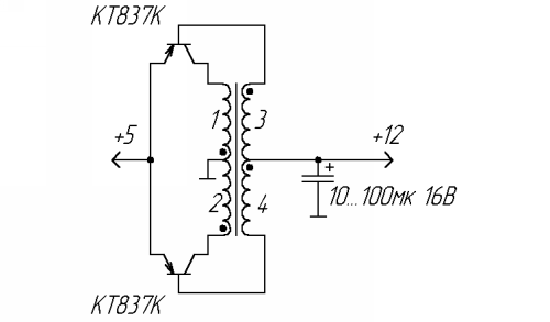
Due to the proportional-current control of the transistors, the switching losses and the efficiency are significantly reduced. The role of diodes, rectifying the output voltage, is played by emitter transitions of transistors.
The magnetic circuit of the transformer is the ring K18 × 8 × 5 from ferrite 2000НМ. Windings 1 and 2 contain 6 turns each, and 3 and 4 consist of 10 turns of insulated wire 0.5 mm in diameter. Each pair of windings are wound simultaneously in two wires.
The inverter is able to operate when the input voltage is reduced to 1V, the required number of turns is calculated by the formula:
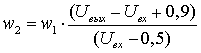
Transistors are chosen based on the allowable values of the base current (it should not be less than the load current) and the reverse voltage of the emitter-base (it must be more than twice the difference between the input and output voltages). For operation in low-power converters, in many cases the transistors KT208, KT209, KT501, etc. are suitable. In this case, the transformer can be made on a circular magnetic core of smaller diameter.
print version
Author: A. Chaplygin, Kursk
PS The material is protected.
![]()

Comments
When commenting on, remember that the content and tone of your message can hurt the feelings of real people, show respect and tolerance to your interlocutors even if you do not share their opinion, your behavior in the conditions of freedom of expression and anonymity provided by the Internet, changes Not only virtual, but also the real world. All comments are hidden from the index, spam is controlled.