|
Start of section
Production, amateur Radio amateurs Aircraft model, rocket-model Useful, entertaining |
Stealth Master
Electronics Physics Technologies Inventions |
Secrets of the cosmos
Secrets of the Earth Secrets of the Ocean Tricks Map of section |
  |
| Use of the site materials is allowed subject to the link (for websites - hyperlinks) | |||
Navigation: => |
Home / Inventions / New types of engines / |
|
ROTARY-WAVE ENGINE
The author of the article: Sedunov IP
|
Today, few people are happy that 60-70% of the heat produced by internal combustion engines is simply thrown into the atmosphere. When energy with its limited raw materials resources can not be reconciled and with 20-30% heat losses within the framework of the same classical thermodynamics, then no doubt will be claimed only those technical solutions that can overcome the main drawbacks of existing thermal machines, borrowing from them only pros. So from the gas turbine unlimited power, small dimensions and weight will be taken; From diesel - high economy; From its gasoline competitor - acceleration and maximum effective use of the engine's working volume; From a virtually forgotten steam engine and its "relative" in the face of modern styrling - noiselessness, multifuel and high torque; From the widely advertised in the recent past of F. Wankel's engine - the absence of gas distribution; From the sensational bezchatunnogo engine S. Balandin and quite an unknown design of E. Lion - high mechanical efficiency and the ability of the engine to perform the functions of the reducer; And from the slightly known engine of V. Kushul - low toxicity of exhaust. |
It will be able to completely or partially abandon: cooling and lubrication, remove the noise silencer, flywheel, and this with a number of parts is not greater than in a two-stroke moto-cycle engine.
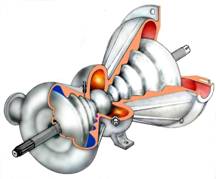
At the current stage of the development of technology this task can be solved only with the transition to qualitatively new internal combustion engines with other constructive principles and solutions. The conceptual idea of the "Rotor-wave engine" (Pat. No. 2155272) , a volumetric co-current machine that reproduces the sequence of operation of a gas turbine engine, fully meets these conditions. It completely eliminates the reciprocating motion of the working bodies, the rotor is completely balanced and rotates at a constant angular velocity. The working body, like in a turbine, moves along the axis of the engine, the trajectory of motion is a helical line. There is no harmful space in the design, which limits the growth of the compression ratio of the working fluid. Due to the lack of sealing elements and, consequently, friction in the flow-through part, restrictions on the resource and engine speed are removed. The working process allows, arbitrarily change the degree of compression and expansion of the working fluid; Without additional adjustments and stop the engine to make the transition to any grade of fuel.
The original kinematic scheme and the progressive working process of the rotary engine make it possible to assemble in one design only the positive sides of all types of ICE . At the heart of the kinematics of the rotary-wave engine (RVD) is a spherical mechanism, where the axes of its main parts intersect in one place - the center of the imaginary sphere.
The conical helical rotor, installed with a minimum clearance, combines the rotation with the opposite planetary rolling around the inner envelopes of the body. Applying these two types of motion to any section of the rotor (except for the center - the point of its inflection), one can see that they perform in a certain sequence equal angular vibrations in the slots of the body, forming waves that are successively rolled along the helical surfaces of the body.
A similar process can be seen on the sea, observing in windy weather the movement of waves in "standing water".
In the compressor compartment, the formation and movement of waves begins from the periphery towards the center, and in the expansion compartment, on the contrary, from the center to the periphery.
|
|
Fig. 1 1- Rotor; 2- Body; 3- PTO shaft; 4- Hinge of equal angular velocities; 5- Eccentric; 6- Gear unit. A - inlet window, B- outlet window, В- compressor compartment, Г- combustion chamber, Д- expansion compartment, φ- angle of inclination of the rotor. |
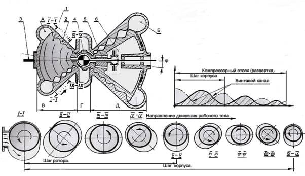
The rotor (1) and the power take-off shaft (3) are interconnected at the center of the engine by the Hook joint (4) , which can be called the hinge of equal angular velocities (SHRUS) . The "additional" rotation necessary for the rotor along the inner envelopes of the casing is set by the auxiliary device - the so-called "wave generator". Its main element is the eccentric (5) rotating on the main shaft, with everything driven by the gear unit (6) from the same shaft. The eccentric tilting the rotor from 3 to 6 degrees provides an angular swing of the rotor cross-sections in the range of 12 to 24 degrees (for more details, see the branch magazine "Drive Engineering" 2 and 3 No. 2001 ). In this configuration, the calculated mechanical efficiency of the engine will be an unprecedented figure - 97% .
With the beginning of the rotation, the helical surfaces of the rotor begin to open the internal cavities of the screw channels of the compressor compartment, sucking them and the air with two streams displaced 180 degrees relative to each other. For one rotation of the rotor, two portions of air are sucked into and cut off from the intake path into both channels of the compressor compartment. With a further rotation, each portion of air begins to move independently to the center of the engine, continuously contracting in the volume due to a decrease in the pitch and amplitude of the winding itself. The compression process will continue until the decreasing volume with compressed air approaches the combustion chamber. At this point, the process of internal compression of air in the compressor compartment will end, the next step is the pushing of compressed air into the combustion chamber by the rear side of the turn, closer to the other located to the center of the rotor. This process is accompanied by a continuous spraying of fuel in the air flow followed by its combustion in a common chamber, where all air portions are expelled. For the initial ignition of the fuel-air mixture in the chamber, a spark plug is installed. After start-up, further ignition of the mixture should be maintained by gases remaining from previous cycles in the common combustion chamber. The latter, with high temperature and pressure leaving the combustion chamber, fill the rotor with screw channels of the expansion compartments located on the other side of the center of the rotor (the points where the pitch and amplitude of the angular oscillations is zero). With the turn of the latter there is an increase in the volume of the expansion compartments due to which the working stroke is realized. At the time of maximum expansion, the edges of the outer turns of the rotor are opened and the gases are first freely, and then forcedly forced into the exhaust manifold. The interval for the exhaust of exhaust gases from the next expansion chamber will be 180 degrees. Part of the power received in the cycle is returned by the rotor body to the compressor compartment.
|
|
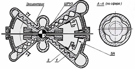
Fig. 2 Pyatigiprotrokhoidnyy RVD with external envelopes and with the selection of power through the hinge of equal angular velocities (SHRUZ) . It has the properties of a reducer - four rotor windings, 20 air volumes are sucked into the engine, one revolution of the output shaft corresponds. Replaces the 80- cylinder piston engine . |
|
|
Fig. 3 Three-hypothrooid RVD with external envelopes and with power extraction through a shaft with an oblique neck. Output shaft and rotor rotate in different directions in a proportion of 1: 0.5 Replaces a 12- cylinder piston engine . |
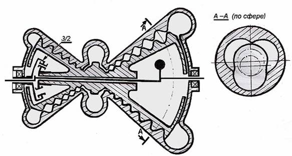
The described work process corresponds to the simplest design, in which the two-pass housing is paired with a single-rotor. The increase in the number of visits inevitably leads to a complication of the shape of the body and the rotor, which will be correlated as whole ordinal numbers: 2 \ 1; 3 \ 2; 4 \ 3; 5 \ 4 , etc. The cross sections of the bodies of the rotor and the body will in all cases have hypotrochoid forms with external envelopes: for example, as shown in Fig. 2 and 3 . Figure 3 shows one of the alternative options for power take-off from the rotor - a shaft with an oblique neck.
The considered type of the engine, which is based on the internal screw engagement of the rotor with the body, forms a new family of ramjet rotary machines: in it, with an increase in the number of rotor and body applications, the angular velocity of the rotor and, correspondingly, the power take-off shaft equipped with a CV joint, will decrease, Of the torque. This remarkable feature of the kinematic RVD scheme will allow the multi-rotor rotor in combination to perform also the function of the reduction gear. It's no secret that the increase in engine power always goes along the way of increasing the working speed (it has nowhere else to go), and the energy consumers, whether it's the ship's screw or the car wheel, remain practically unchanged. It is necessary to put additional reducers to reduce the speed. And here, the engine to itself and the reducer.
The function of the gearbox in multi-input structures (Fig. 2) is assigned to the synchronization mechanism consisting of a stationary ring with internal gearing (1) and a smaller planetary gear with an external gear (2) rigidly connected to the rotor. The number of crown teeth to the gear must always correspond to the selected proportion of the body to the rotor. Otherwise, it is impossible, only this achieves synchronization and the required trochoid movement of the rotor. Each new rolling of the rotor gear will be matched by its rotation to a fixed angle with the rotor. For a twin-rotor rotor, which is paired with a three-aisle casing, the rotation of the rotor in the casing is 50% , the rotor rotation by 33% , the four-way rotation - by 25%, and so on.
If initially a single-rotor rotor, working in pairs with a dual-hull body is equivalent to an eight-cylinder piston ICE , then the two-rotor rotor is paired with a three-way hull equivalent to a 24- cylinder ICE . Further more. A three-rotor rotor corresponds to a 48 cylinder piston engine , a four-stroke rotor to a 80- cylinder ICE, and so on.
For the last example, which will have a slightly lower mechanical efficiency (94 -95%) , the estimated torque on the output shaft will increase from 16 to 21 times in comparison with the piston analog, and this with equal engine speed and engine speed. That in itself, for example, for the car version no longer requires the installation of a gearbox behind the engine, which increases the engine torque only 4 to 10 times .
Here the rotor, producing a full revolution, is forced to make four complete runs around the inner envelopes of the hull. Accordingly, at 2500 rpm of the rotor, each of the five screw channels of the casing should suck in 10,000 volumes of air, which in total will be 50,000 volumes per minute . For comparison, in a similar single-cylinder four-stroke ICE at equal revolutions, the number of suction strokes will fill 625 engine working volumes (every fourth stroke is suction). That's where it comes from, eighty times the difference. Given the low filling ratio of the naturally aspirated piston engine, equal to 85% versus 100-105% in the WFD , the actual difference will increase to 94 . We did not take into account the difference in the mechanical efficiency of the piston engine and the RVD, respectively, 85% against 94% . We shall correlate it to the leakage of the working fluid through the "looseness" of the rotor.
It remains to mention the maximum permissible RPMs, comparing them with the serial engines. Modern piston engine uses 4500 - 6000 rpm ; Similar in capacity gas turbine is freely untwisted up to 50,000 - 70,000 rpm ; RVD should take an intermediate position - its share from 2500 to 30,000 rpm (all depends on the number of rotor inputs).
In the working compartments of the WFD, it can simultaneously contract and expand from several units to several tens of air volumes. And the place where the rotor, almost touching its surface, is approaching the minimum distance to the body, is just a moving dividing line between successive moving chambers (in Fig.1, sections 1-1 and 1X-1X) . For each rotation of the rotor, the degree of compression (expansion) changes 4-5 times. Theoretical degree of compression (expansion) in one unit can reach one hundred units (all depends on the number of turns), and this is with complete failure of the sealing elements, the role of which is performed by the body of the rotor.
The rotor, free from mechanical friction, "screws up" portions of air into the combustion chamber, nowhere touching the walls of the housing, so there is also no need to lubricate the engine's engine compartments. The friction remains only in the rolling bearings on which the rotor rests outside the hot zones and in the CV joint . The latter is structurally very easy to transfer the entire flow of power from the rotor to the output shaft in fact without loss. Suffice it to recall that the mechanical efficiency of widely used SHRUS technology is very high and fluctuates at small swing angles from 99 to 99.5% . In addition, the articulation automatically automatically centers the rotor in any position, and the hinge located in the center of the engine is reliably protected from the thermal action of the combustion chamber by the required thickness of the spherical heat shield.
As we can see, in the RVD nothing prevents the use of very high speed: the rotor rotates at a constant angular velocity, it is perfectly balanced, instead of valves, or even windows, the channel uses unlimited bandwidth for continuous airflow into the engine's working compartments. Absence of friction and removes the limitations on the wear of parts and the life of the engine as a whole. In the engine, only bearings will wear out, and for them a resource of 30 - 40 thousand working hours is not the limit. Note by the way, that a good car engine in our time has a motor life of 5000-7000 hours before the first repair. Automobile RVD , with unlimited power will be more durable than the frame of the car (the most durable that is in it).
The working process for a constant combustion chamber allows, without stopping the engine, to supply any kind of liquid, gaseous or even solid atomized fuel into it, completely erasing the boundaries between turbines, diesel and carburetor engines.
In the kinematic links of the mechanisms of piston and rotary internal combustion engines there are so-called "dead points", to overcome them, a large mass flywheel is installed behind the engine. In the WFD , the gas forces acting on the rotor are always directed along the tangent to its surface, they are constant and continuous, which makes it absolutely unnecessary to install the flywheel, and in some cases also the counterweights used for complete balancing of the engine.
The layout of the compressor and expansion compartments of the ROV is such that it allows and, without stopping the engine, within a wide range, to vary the degree of compression and expansion of the working fluid, including up to a complete expansion of the exhaust gases, which eliminates the need for a noise silencer. Disappear is not only the considerable resistance that the muffler creates, taking away up to 10% of its power from the engine, but also in the process of continued expansion another 10-15% of the additional energy will be released.
Of course, the power increase of 20-25% is very attractive for developers of serial ICEs. In practice, however, the continued expansion can not be used because of the inexpedient increase in the weight dimensions of power plants, while the magnitude of the mechanical losses increases in them.
And, finally, the main reserve for improving efficiency is the use of ceramic materials in the RVD design - heat-resistant thermally insulated coatings, which allow to abandon the cooling system and replace the most complex turbo-compound engines. Using only the properties of the ceramic for the RVD , which she always had - the ability to work on compression, moderate stretching at a stable temperature and pressure in all sections of the body and the rotor.
In conclusion, we give a few more figures. The calculated indicator efficiency of a simple HVAC cycle in adiabatic execution and a very moderate compression ratio of 15 with an expansion ratio of 36 will be 51% . Accordingly, fuel consumption in this case can reach 171 g / kW , with a specific weight of the power plant 0.15-0.25 kg / kW . For comparison - in a diesel engine using such a compression ratio, fuel consumption is 224 g / kW at a specific weight of 3.5 to 15 kg / kW . Due to the further increase in the compression ratio in the RVD and the use of the exhaust gas reclamation system (for recovering the heat lost with the exhaust gases), the indicator efficiency of the thermal cycle can be significantly increased.
Wherever it is required to obtain the maximum air flow and huge capacities, for example, for aviation and ship installations - it is more profitable to use multi-path kinematic schemes limited by the increase in the compression ratio. If economy is the main factor, it is more promising to use two-three-pass rotor circuits, which are the simplest and allow the greatest degree of compression and expansion of the working fluid.
It is necessary to recognize that at the moment the technological base of enterprises that can be attracted for the manufacture of such a class of machines is lagging far behind, but at the same time the intensive development of computer design is able to solve many technical issues, thus opening favorable conditions for the creation of highly economical and environmentally safe power plants .
print version
Russia tel / fax: (812) 379-17-32
Author: Sedunov I.P.
PS The material is protected.
Date of publication 23.09.2004гг
![]()

Comments
When commenting on, remember that the content and tone of your message can hurt the feelings of real people, show respect and tolerance to your interlocutors even if you do not share their opinion, your behavior in the conditions of freedom of expression and anonymity provided by the Internet, changes Not only virtual, but also the real world. All comments are hidden from the index, spam is controlled.