
| Start of section
Production, amateur Radio amateurs Aircraft model, rocket-model Useful, entertaining |
Stealth Master
Electronics Physics Technologies Inventions |
Secrets of the cosmos
Secrets of the Earth Secrets of the Ocean Tricks Map of section |
  |
| Use of the site materials is allowed subject to the link (for websites - hyperlinks) | |||
Navigation: => |
Home / Inventions / New types of engines / |
|
ROTARY INTERNAL COMBUSTION ENGINE
CONSTRUCTIONS OF MAKAROV
Yuri Makarov
Patent publication number: 2143079
Registration number of the application: 98103181
It was created in terms of further development and improvement of the designs of internal combustion engines in general and the rotor - piston engine of the Wankel design in particular, which can be adopted as an analogue, the closest in design.
The engine is designed for use in all types of land and water transport, light aircraft and stationary power plants. When designing the engine, the principles of a pneumatic motor and a high-pressure plate hydraulic pump were taken as a basis. Having united which in one design and it was possible to receive the new engine .
In the construction under consideration, there are no crank-connecting rod, piston and gas-distributing mechanisms. And the working element, the rotor, has an absolutely circular shape and rotates uniformly around its axis, which is why the entire unit is well balanced. In this case, one revolution of the rotor corresponds to one revolution of the shaft, and not three, as in the Wankel engine . Moreover, the torque on the shaft is created by applying the energy of the expanding gases to the working plates located in the radial grooves along the perimeter of the rotor. Due to which the applied force is directed along the tangent to the rotor, and the arm of the application of force, constantly exceeds its radius. At the same time, the internal surface of the rotor can be used as a centrifugal blower of the working mixture, which results in excess suction pressure, and additional cooling and lubricant supply to the working plates, the rotor and its bearing assembly.
Due to the absence of the gas distribution mechanism in the engine, the use of the rotor as a centrifugal blower and the constant presence of several working cavities in the suction phase, we completely exclude the harmful pulsation of the flow of the fuel mixture. And in connection with the excess pressure on the suction, the possibility of adjusting the duration of this stroke to the required limits, we obtain a stable high filling factor, and hence torque and power in the entire range of engine operating speed.
To achieve similar results, the engine in question embodied only the best sides of the piston, rotary piston and gas turbine engines . And by applying new technical solutions it was possible to significantly expand the range of solved problems currently facing internal combustion engines . Including:
Use a logical, not contradictory general principle of construction and operation of the engine ;
Create an engine that does not have parts that perform reciprocating movements and are rigidly connected with the working body;
To achieve a high torque in a wide range of engine speed, to ensure control of the duration of the suction strokes and the working stroke within the required limits;
In order to improve the economy of the engine at partial loads, ensure the presence of a mechanism for smoothly changing the working volume to the required extent, without changing the compression ratio;
In order to improve the filling of working cavities with a fresh fuel-air mixture, use the inner surface of the working element, the rotor, as a centrifugal blower.
To ensure the optimal process of combustion of the working mixture and, accordingly, to reduce the toxicity of the exhaust gases, to provide the necessary trajectory of expansion of combustion products during the strokes of the working stroke and the release of catalysts passing in the active medium (option);
In order to increase the efficiency and power / mass ratio, to provide four full strokes - suction, compression, working stroke and release, per one revolution of the shaft with minimum dimensions and engine weight;
Provide maximum simplicity of construction with a small number of parts. And simplicity of manufacturing and assembling the engine ;
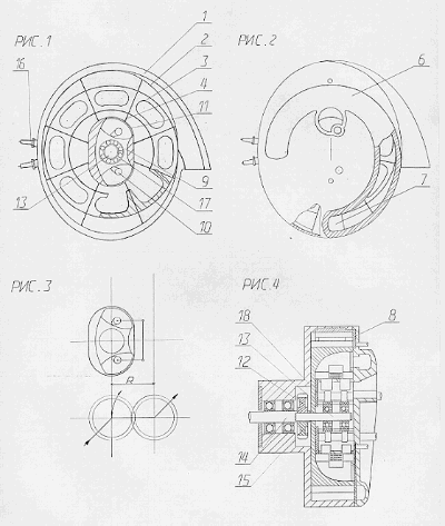
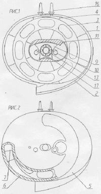
The appearance, internal structure and principle of the engine operation are shown in Figures 1-4:
 |
 |
|
Fig.
1 The internal arrangement of the engine . Cut-out on the plane of the connector body-front cover.
| |
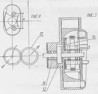 | |
The shape of the hemispheres can be different and depends on the characteristics that need to be obtained from the engine in each particular case. The hemisphere in which pass the steps of the working stroke and release, smoothly passes into the exhaust manifold, and is part of the hull. The suction of the working mixture takes place in the opposite hemisphere and is carried out through a suction manifold located in the front cover of the engine . In the front part of the engine casing - in the working cavity, the working body of the rotor with radially located "floating" working plates is located. In the rear part of the body, behind the rotor, there is a single-stage gear reducer, which, during engine operation, continuously transmits the main flow of torque developed by the working member to the output shaft of the motor , regardless of the vertical displacements of the rotor and the drive shaft when the working volume of the engine changes . In this case, the driving gear ( 12 ) located on the axis of the rotor ( 13 ) moves along a path with a radius R equal to the distance between the rotor axes and the output shaft of the motor ( 14 ). Running the driven gear ( 15 ) located on the output shaft of the motor along the diameter of its pitch circle. The corresponding trajectory of displacement is given by the displacement unit of the working volume, the lateral contiguous sides of the sleeves ( 9 and 11 ) of which are machined with the curvature of the corresponding radii.
The same device, with the appropriate selection of the diameters of the gears of the reducer, maintains a constant compression ratio with a change in the working volume of the engine . Since when the axis of the pinion moves from the position corresponding to the minimum working volume when the horizontal axes of the pinion and wheel coincide with the maximum, along the trajectory of radius R, it does not only vertical but also horizontal displacement, thereby increasing the volume of the combustion chamber at the time of maximum compression.
The main working element of the engine is a rotor, it has a circular shape and rotates uniformly around its axis, which results in a good balance of the engine . In this case, the rotor having a relatively large diameter is used not only as an operating element and a centrifugal supercharger, but also serves as a flywheel.
Suction, compression of the working mixture, working stroke and exhaust of exhaust gases occurs due to rolling by "floating" working plates radially located in the rotor, internal surfaces of the hemispheres of the working cavity of the housing.
In the first hemisphere, the strokes of the suction and compression of the working mixture proceed. In this case, the fuel mixture is fed through the hole in the front cover and enters the cavity of the bushing ( 11 ). From where it is sucked off by a rotating rotor along the way cooling and lubricating the bearing assembly, working plates and the rotor itself. And only after that, under excessive pressure, it is injected into the suction manifold. In order to optimize the process, the duration of the suction stroke is adjusted within the required limits by a slat damper located on the front cover of the engine and regulating the length of the suction manifold.
After passing the compressed working mixture past the spark plugs ( 16 ), its ignition occurs, and then in the second hemisphere - expansion - the working stroke and release.
In order to ensure a better ignition of the compressed working mixture, as well as the optimal combustion process and the minimum toxicity of the exhaust gases, the entire surface of the second hemisphere, including the exhaust manifold, can be coated with a catalyst bed. Thus, the entire combustion process takes place for the first time in an active catalyst medium. In this case, the energy of the expanding gases acts on the working plate, creating through it the torque applied to the rotor.
After the passage of the initial edge of the exhaust manifold formed by a special gate, which controls the beginning of the exhaust stroke, the exhaust gases begin to break through the collector into the exhaust zone, thus continuing to act on the working plate until the end of the exhaust stroke, but according to the principle of the gas turbine engine .
The front cover is the most difficult and at the same time the bearing part of the engine . On it there are a suction collector, gates of systems for regulating the duration of the suction and exhaust strokes, as well as a unit for changing the working volume of the engine , combined with a single bearing unit of a cantilever fixed in the rotor. The front part of the shaft ( 13 ) located in the bearing assembly acts as a rotor bearing element and transmits the torque only to drive the auxiliary units (pump, generator ... fixed to the outside on the front cover) and rotates in two rolling bearings ( 17 ) located In the movable bushing ( 9 ) of the mechanism for changing the working volume. The movable bushing, in turn, with the help of two eccentrics ( 10 ) together with the bearing unit, the shaft and the rotor, can move within certain limits inside the bushing ( 11 ) thereby changing the volume filled with the fresh fuel mixture within the preset limits (changing the engine displacement ). Together with the cover ( 18 ) of the engine displacement unit , the whole construction forms one common and compact unit: the front cover is the rotor.
To ensure the necessary compression, as well as the separation of the working segments of the rotor in different working cycles, a reliable seal between them is required, provided by working plates of a special shape.
The main sealing force is created due to the centrifugal force acting on the plate and the rotor, which rotates with the operating speed, which arises.
When the rotor rotates at a speed that does not provide the necessary centrifugal force, for example, when the engine is started, the required sealing force is created by a flat spiral spring that repeats the trajectory of the working plates and inserted into the rotor. In order to prevent rotation, one end of the spring is fixed to the front cover of the case, and the second, the inner one is free. Due to this the spring is constantly in working condition and gradually moving apart compensates wear of the working plates.
In this description, all the possibilities inherent in the design of the engine are schematically reflected . And such functions as the use of the rotor as a supercharger, the change in the working volume and the duration of the timing phases are options and demonstrate additional design possibilities.
And a different engine power system is preferred when the injector is located on the housing in the vicinity of the spark plugs, thereby providing a direct fuel injection system.
Attention! I will be glad to receive reviews of my development and constructive proposals, including about mutually beneficial cooperation.
print version
Author: Yuri Makarov
PS The material is protected.
Date of publication 03.10.2006гг
![]()

Comments
Commenting on, remember that the content and tone of your message can hurt the feelings of real people, show respect and tolerance to your interlocutors even if you do not share their opinion, your behavior in the conditions of freedom of expression and anonymity provided by the Internet, changes Not only virtual, but also the real world. All comments are hidden from the index, spam is controlled.