
| Start of section
Production, amateur Radio amateurs Aircraft model, rocket-model Useful, entertaining |
Stealth Master
Electronics Physics Technologies Inventions |
Secrets of the cosmos
Secrets of the Earth Secrets of the Ocean Tricks Map of section |
  |
| Use of the site materials is allowed subject to the link (for websites - hyperlinks) | |||
Navigation: => |
Home / Inventions / Alternative energy / |
|
The phenomenon of direct conversion of the energy of the magnetic field of permanent magnets
And its application in power engineering and mechanics
Dudyshev Valery Dmitrievich, Russia, Samara
Samara Technical University
Valery Dmitrievich Dudyshev
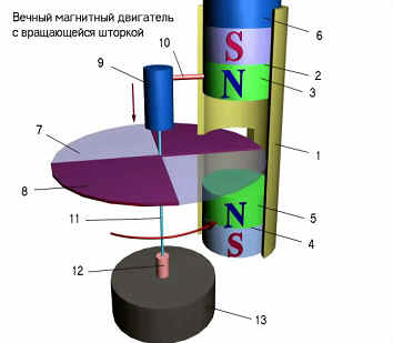
Magneto-gravitational engine with rotation of ball magnets on rod
Magneto-gravitational engine "yula" with segmental screens and displacement
Magnets in the vertical plane
The global and increasingly increasing energy and environmental crises of the planet prompts scientists and engineers to actively seek new alternative environmentally friendly efficient sources of energy, including, on the basis of permanent magnets and electrets.
The known magnetic motors (MD) of Searle, Minato, Floyd are still very imperfect, unfortunately, however the beginning of history with the emergence and development of MD has already been laid. The article presents new original designs of new, completely non-current MDs. Despite the fact that the nature of magnetism is not yet fully understood, even now, permanent magnets really bring us closer to the revolution in energy and mechanics. Powerful progress in the field of permanent magnets allows us to hope for the creation of magnetic motors - generators and other useful devices based on them - up to 100 -200 kW already in the near future.
Let us begin our consideration of the ways of creating purely magnetic motors with the simplest magneto-gravitational engines (MHD) - magnetic pendulums and rotational MHDs.
![]()
In Fig. 1 shows the simplest pendulum magneto-gravitational motor with two magnets-an immovable permanent magnet 6 and a movable magnet 1 placed by the same magnetic pole to repel with a minimum gap in a hollow nonmagnetic tube 3 with a return spring 2 and an abutment 5 . Under the action of repulsive forces of the same magnetic poles, the movable magnet 1 begins to perform cyclic vibrations in the vertical plane. The left part of the figure shows the position of the elements of this simplest magnetomechanical system "magnetic pendulum" at the upper point of the pendulum 3 lift due to the energy of the magnetic fields by repulsing two magnets 1 and 6 . First, the left part is raised together with the hollow tube 2 upwards and pushing away from the magnet 6 - it simultaneously winds the spring inside it (the extreme position of the magnet 1-1 and the compressed spring 2-1 after the pendulum returns to the bottom point to the base 5 ). Further, under the action of gravity, the tube again rushes downward and when the spring is straightened, the force of repelling the magnets again increases, and the process repeats cyclically. Thus, this magneto-gravitational device performs a combined oscillatory and reciprocal translation of the magnet 1 relative to the magnet 6 , i. E. Makes a direct conversion of magnetic energy into mechanical energy.
Fig. 1
![]()
A more perfect design of the magneto-gravitational rotation engine (MHD) is shown in Fig . 2 . It consists of a non-magnetic cylinder-rim 1 fixed on a horizontal axis on a vertical support 6 . On the outside of this axis and inside the rim 1 is placed a cylindrical magnet 2 with a radial magnetization and the axis of the magnetic equator coinciding with the vertical axis of the support 5 . Inside the rim of the rotor 1, there is also an arc permanent magnet 3 with an inner radius equal to the outer radius of the magnet 2 on a movable radial axis 4 at the end of which a metal ball 5 is fixed. To increase the energy efficiency of such a motor, a spring mechanical energy storage device On the axis 4 between the rim 1 and the magnet 3 . The spring in Fig. 2 is not shown. The number of such spring-magnetic rods can be more than 1 . In this case, they are placed symmetrically on the rim 1 . Such a design will only increase the power of the engine with unchanged dimensions. To start this MHD into operation, it is necessary to make several initial revolutions of the rim 1 by the starting device. Then the motor works autonomously. Rotation of the rotor 1 is due to the fact that the rotational moment of the disk rotor 1 from the total gravitational force and the magnetic repulsion force of the magnets in the accelerating left portion of the rotor path of the rotor 1 is greater than the braking torque when lifting the load 5 . Because the different radii of rotation of the load 5 due to the force of magnetic repulsion of the magnets 1 and 3 on the left half-turn of the rim 1 (rod 4 extends). And on the return half-cycle-half-turn of the rim 1- right-the magnets 2,3 tend to attract and therefore the radius and the moment of rotation of the load 5 on this interval becomes smaller.
The power and speed of the rotor-gear 1 are adjusted by turning the central cylindrical magnet 2 around the axis or by other means, for example changing the working gaps between the magnets, the length of the rod 4 . With the correct choice of magnets 2,3 and load-ball 5 the device works steadily. It can be performed at different capacities. The more the magnetic induction of permanent magnets and the higher their mass - the higher the mechanical power of such a motor.
Its scope is very wide - from souvenirs to power fuelless drives of many types of transport.
If you install such a magneto-gravitational motor on a flat floating platform and equip this rotor with blades, it will accelerate without apparent causes for the external observer. The mechanical power on the shaft of the blade drum MHD and the speed of the vessel is provided by exclusively the magnetic and gravitational energy of this original motor - or rather due to the pulling pulses of attraction and repulsion of the rotor magnets relative to the stator magnet. Moreover, such a fuel-free MHD can simultaneously generate an electric current of an alternating current into the load, in the event that inductive windings are also placed on its rim 1 . Naturally, the total mechanical power and generated total energy of the motor-generator do not exceed the power and energy of interaction of magnets and gravitational forces. They directly depend on the size of the MHD design, the mass and properties of the magnets 2,3 and the ball-load 5 .
Fig. 2
![]()
Magnets in the vertical plane
Everyone knows the children's toy "yule" - it turns out - may well become - after some modernization - an eternal magnetic motor. This MD design is shown in Fig. 3
|
Fig. 3 |
For the most effective use of the force of gravity in MHD, a "magnetic yule" design is proposed in which permanent magnets perform reciprocating motion (Fig . 6) . This MHD consists of a horizontal disk 8 partitioned by magnetic shields 7 and a spring mechanism 9 , connected by its housing via a lever 10 with a movable permanent magnet 2 , to a load 6 located in a vertical non-magnetic pipe 1 with inserted in it Pairs of permanent magnets 2 , 4 towards the same magnetic poles 3 , 5 to repel the upper movable upper magnet 2 from the stationary lower magnet 4 . The principle of operation of such an MHD is that the magnet 2 moves upward under the action of magnetic repulsion forces from the magnet 4 , in the absence of a magnetic shield 7 between them. Conversely, in the next half cycle of the MD-magnet 2 moves downward under the action of the gravitational force when the magnets 2 , 4 are shielded by the screen curtain 7 when the segment disk 8 rotates. Rotation of the disc is carried out according to the principle of yule by cyclic compression - straightening of the spring inside the cylindrical cage 9 with the reciprocating movement of the lever 10 mechanically connected with the movable magnet 2 and the return spring inside the cage 9 . The speed of rotation of the disk depends on the design parameters of the MHD, the mass and the properties of the permanent magnets used. An electric generator 12 can be mounted on the axis 11 . The advantage of these MHDs is the full use of magnetic forces repelling permanent magnets. |
![]()
Let us consider another method of direct conversion of exclusively one magnetic energy of permanent magnets (PM) to the mechanical energy of their mutual rotation by using the inhomogeneity of their magnetic fields at the magnetic poles and the magnetic equator of these PMs. The most characteristic variants of the designs of such polar MDs are shown in Fig. 4-6 . Due to the heterogeneity of the magnetic field of the central stator magnet and the rotor magnet, the moment of inertia of the magnet of the rotor and the continuous alternation of the attractive forces-repulsion of the magnet poles at different sections of the trajectory of the permanent magnet of the rotor, all these devices of polar MDs, as shown by experiments, are fully operable.
A) a magnetic motor with a rotor magnet movable in the axial plane - Fig. 4.
After the initial removal of the PM of the rotor 2 together with the rim 3 to the z-position between the magnetic equator and the pole of the stator 1 PM, the initial orientation of its poles to mutual attraction to the opposite magnetic pole of the central stationary stator magnet and the initial push of the rotor magnet 2 toward the nearest magnetic pole of the central Magnet 1, the movable magnet-rotor 2 begins to accelerate at the top dead center spontaneous axial and orbital rotation around the central stationary permanent magnet 1 . By inertia, it passes through the zone above the magnetic pole of the central PM and then repels itself with its power lines from the poles of the stator magnet 1 of the same name. After passing the magnetic equator, PM1 starts to turn 180 degrees. Experiments have shown that the movable magnet 2 sometimes automatically and automatically makes four or more axial turns on the axis of the strengthened platform 4 for its full orbital revolution - but its automatic reversal is noted about the axis after passing the line of the magnetic equator of the central fixed magnet 1 in the space on the axis of its plane in such a way Way, to fly the opposite pole to the near opposite pole of the central PM along the trajectory of its orbital rotation together with the rim 3 . In fact, this is a simplified physical model of a natural magnetic motor in the solar system (the interconnected spontaneous axial and orbital rotation of a permanent magnet relative to a central permanent magnet).
B) an orbital magnetic motor with a central compound magnet-a quasi-monopole-and an orbiting rotating magnet- Fig. 5.
For the first time, the construction of a fully contactless MD with a compound magnet by a quasi-monopole of a reversed stator is proposed. Therefore, the rotor magnet 2 is rigidly oriented on the rim 3 along a tangent to it. The analysis of the interaction of the magnetic forces of the moving magnet of the rotor 2 with the total magnetic field of the quasimonopole 1 of the stator of such a MD shows the presence of an unchanging accelerating force of the magnet 2 in all parts of its orbit. Indeed, the magnet of the rotor from the point 2-1 of the magnetic equator will be accelerated towards the point of the magnetic pole of the quasimonopole 1 . At the point of symmetric placement of the strip permanent magnet of the rotor = as shown in Fig. - at the pole of the central quasi-monopole - perpendicular and symmetric with respect to the polar axis of the quasimonopole - the force of their magnetic attraction is zero because both halves of the magnet 2 are located equally in range from this pole of the quasimonopole. Hence the force interaction of the poles-halves of the magnet-rotor is also the same - but opposite in sign. If there was a rotor magnet. In the case of its mobility on the axis, the rotor magnet would begin to rotate along the axis by the opposite end to the pole of quasimonopole 1 - but it is fixed rigidly to the rim - therefore, by inertia it will slip along this rim of magnet 1 along with rim 3 .
But as soon as the rotor passes the point of the pole of the quasi-monopole by inertia, then the force of magnetic repulsion - to the point of intersection with the magnetic equator of the quasimonopole 1 - begins to act. After the magnetic line of the magnetic equator (ME) passes through the magnet 2, the force of magnetic attraction of the pole of the rotor magnet to the opposite pole of the magnetic monopole again starts to act, due to the inhomogeneity of the monopole MP and the thickening of the magnetic field lines near its second magnetic field, i.e. Will move to the opposite pole in the direction of condensation. Thus in this MD there are alternating attractive forces and repulsive forces of these magnets. The attraction force of magnets 1,2 operates from point 2-1 to the approach of the magnetor to the opposite pole of the quasimonopole-this force of attraction of magnets towards increasing the density of the magnetic field lines to the opposite pole of the quasimonopole-this force is nonlinear and increases as one approaches the trajectory of the rim Pole of the quasimonopole and acts on the section from the magnetic equator to the pole of the quasimonopole. Then there is the repulsive force of the magnets right after the magnetic pole of the quasimonopole crosses the magnet of the rotor. This repulsive force of the same poles of magnets acts from the pole to the magnetic equator over the second half of the trajectory of the magnet 2 around the quasimonopole 1 - in comparison with the starting point 2-1 and it is also nonlinear and maximum immediately behind the magnetic pole of the magnet 1-1 and then decreases and Is equal to zero on the magnetic equator.
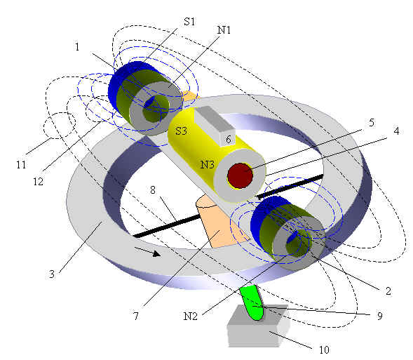
C) an orbital magnetic motor using the effect of a slightly expensive and rapid magnetization reversal of a stationary stator PM with a rectangular loop of the hysteresis-effect of the magnetic trigger - the Barkhausen effect - Fig. 6.
The constructions of these MDs are shown only in the main foreshortening and simplified. The essence of his work is similar to MD - in Fig.
6. To increase the force of interaction of permanent magnets along magnetic lines of force, additional magnetic cores, special forms of magnets and minimal gaps between them are also needed.
Fig. 4
Fig. 5
![]()
1. For the first time, a completely magnetic bearing, a disk magnetic reducer and fully magnetic motors of various types have been proposed and investigated.
2. Methods of transformation of magnetic and gravitational energy in a single design of magnetic motors with their work on a closed cycle and various designs of magneto-gravitational motors of different types (oscillatory, rotational) are proposed.
3. The proposed designs of magnetic motors, non-contact magnetic gearboxes and bearings open the prospect of creating a new fuelless and efficient magnetic power and mechanics
4. The proposed polar magnetic motors can also be realized in cosmonautics to create an "eternal" orbiting magnetic satellite of the Earth-a natural magnet-and other planets with magnetic fields.
|
Fig.6 Magnetic motor with polar orbit of rotation of permanent magnets and polarity switching of the central magnet - Barkhausen effect 1. Permanent magnet |
OPERATING PHYSICAL MODEL OF THE MAGNETOGRAVITATIONAL ENGINE
Literature
1. Commercialization of the Searle effect in energy and in the field of new propulsion systems - review - "New Energy" 2/2004.
2. VD Dudyshev New Fuelles Spage Pover Engineering-New Energy Technologies-decemder 2002
3. VD Dudyshev Latent Potential Energy of Electrical Field - New Energy Technologies -Juli2003
4. VDDudyshev. The method of extracting internal energy from substances - "New Energy" 3/2004 g (in press)
print version
Author: Valery Dudyshev
PS The material is protected.
Date of publication 22.08.2004гг
![]()

Comments
When commenting on, remember that the content and tone of your message can hurt the feelings of real people, show respect and tolerance to your interlocutors even if you do not share their opinion, your behavior in the conditions of freedom of expression and anonymity provided by the Internet, changes Not only virtual, but also the real world. All comments are hidden from the index, spam is controlled.