| section Home
Production, Amateur Radio amateur Model aircraft, rocket- Useful, entertaining |
Stealth master
Electronics Physics Technologies invention |
space Mystery
Earth Mysteries Secrets of the Ocean Stealth section Map |
  |
| Use of material is permitted for reference (for websites - hyperlinks) | |||
Navigation: => |
Home / Inventions / Alternative Energy / |
|
Fuel-free magnetic motor Alekseenko
Russian Federation Patent RU2131636
![]()
Alekseenko Vasily Yefimovich
Use as a rotary drive. The engine consists of a disk (flywheel) mounted on the axis. It mounted one or more permanent rotor magnets which together with the disk (flywheel) can rotate freely around the axis. In parallel, the working disk (flywheel) motor on the stem are fixed cylindrical permanent magnet stopper, which, together with the rod can move within range of the magnetic fields of the permanent magnets in the rotor located on your disk. All magnets are facing each other like poles. Like poles repel each other and force the engine working disk to rotate around its axis. The engine runs on the energy of the strong magnetic fields of the permanent magnets due to the difference of magnetic potential energy at the poles of the rotor magnets and neutral zones. The technical result consists in the fact that to create the rotation, fuel consumption is minimal.
DESCRIPTION OF THE INVENTION
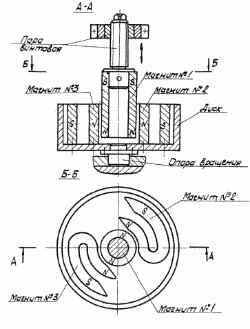 Fig. 1 |
The closest in technical essence to the proposed solution is a magnetic motor (vibrator) comprising a stator in the form of an annular permanent magnet and a rotor (armature) in the form of rod-shaped permanent magnet disposed inside the stator in one with it a plane with the possibility of interaction between the like poles ( a. a. of the USSR N 1658310, H 02 K 33/00, 1988). Its disadvantage is that it needs a supply of electricity. The aim of the present invention is to provide I eco-friendly, without the engine exhaust, which does not require the consumption of fuel and energy supply from the outside, does not pollute the air and the atmosphere of the environment. The engine will run on the energy of the strong magnetic fields of the permanent magnets located on the engine. Permanent magnets for a long time retain their strong magnetic fields and can be re-magnetized. The stability of the magnetic fields of the permanent magnets is saved and when the engine thanks to the continuous rotation, ie, the movement of negatively charged electrons in their closed orbits around the nucleus of an atom of matter, from which built the magnets. In its rotation along closed orbits of the electrons create a circular electric currents, around which the law on magnetism and a magnetic field, which is the inseparable companion of every current. A consequence of this transformation occurs and continuous replenishment of the magnetic energy in the permanent magnets. That is why the magnetic fields remain stable and during engine operation. |
Therefore, the fuel-free engine and does not require fuel and energy supply from the outside.
Fuelless engine power may be different, which is determined by three factors:
- The increase of the engine shoulder. This is achieved by increasing the diameter of the stator and thus to him rotor diameter.
- The use of permanent magnets with a strong magnetic fields.
- Increasing the disk array, which is also the engine flywheel. Since the drive motor is capable of up to twenty thousand revolutions per minute, even a small increase in mass of the disk (flywheel) torque moment it will correspondingly increase, at the same time and will increase the engine power.
Environmentally friendly fuel-free engine can be widely used in automotive, tractor, aviation, space, underwater transport, energy, public utilities, and many other sectors of the economy.
ENGINE
Fig. 1 is a perspective view of the disk of the engine mounted on a working axis (top view). In the plane of the disk can be installed and secured one or more permanent magnets.
In this embodiment, as shown in the diagram on the plane of the disc are fixed two permanent magnets (№2, №3), which together with the disc can rotate freely on the drive shaft. In parallel, the working drive motor on the stem are fixed permanent magnet №1, which, together with the rod could get mixed up in the zone of the magnetic fields of the magnets (№2, №3). All magnets (№1, №2, №3) facing each other like poles. Therefore, when administered magnet №1 using rod magnets coverage area (№2, №3) of N pole magnetic field interact. They are formed, and their resulting repulsive moment increases. Herewith the horizontal repulsion forces at №1 magnets (stator) directed radially to the conical surfaces of the ends of the N pole magnets and №2 №3 (rotor). Since the disc with the magnets №2 №3 and has a degree of freedom and can rotate freely around an axis under the influence of the repulsive force of the magnet №1 (stator) acting on the surface of the conical ends of the poles N (rotor) disk and makes the turn around. Consequently, there is a continuous and disk rotation, i.e. (Rotor) around the axis.
Rotation of the drive magnets and №2 №3 occurs, as shown, in a clockwise direction.
Switching off the work fuelless engine occurs at the withdrawal of the magnet from the magnetic field №1 coverage №2 and №3 magnets.
When designing the disc magnets must be borne in mind that the length of the magnet should be such that the center of its neutral zone magnetization remained close to zero. This will respect the differences of magnetic potential energy (magnetization) between the magnet poles and the neutral zone, as due to the difference of magnetic energy potential and there is a continuous drive of the engine rotation.
|
Fig. 2 shows a second embodiment of a magnetic motor, where mannitol shows №1 (stator) having a shape of a circle fixed to a support. In parallel, a magnet is a horseshoe magnet №1 №2 (rotor) which is fixed to the rod on the disc. N and S pole magnet №2 are tapered at an angle of 40-45 degrees. Disc magnet №2 using stem can climb and descend to the surface of the end of poles N №1 magnet. Magnets №1 and №2 are directed to each other like poles. When lowering the magnet №2 using the rod to the end surface of the magnet pole N №1 on a short distance of the magnetic field of the poles N reacts. They are formed, their resultant repulsive moment increases. This gives rise to a repulsive force from the N pole magnet end №1 (stator) in a vertical direction along an axis directed toward the surface of the conical end of magnet poles N №2 (stator). |
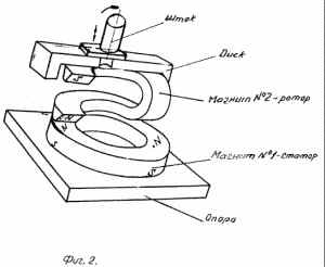 Fig. 2 |
And since the drive magnet № 2 has a degree of freedom and can rotate freely around an axis under the influence of a repulsive force end pole N magnet № 1 (stator) acting on a conical surface end pole N (the rotor) and causes the disc to rotate in a circle. Consequently, there is a continuous rotation, and the motor drive, i.e. (Rotor) around the axis in a clockwise direction.
Turning work fuelless engine occurs at the withdrawal of the magnet from the magnetic field №2 coverage magnets №1 using stem.
The use of environmentally friendly engine fuelless eliminate the pollution by exhaust fumes and other harmful substances atmosphere of the air and the environment of our planet.
CLAIM
The motor for rotary motion having fixed parallel to the permanent magnet rotor permanent stator magnet having the opportunity to move into the zone of action of the magnetic field of the permanent magnet of the rotor, wherein the permanent stator magnet fixedly mounted on the rod, through which it is injected into the action of the magnetic field zone permanent magnets in the rotor, configured as a disk (flywheel) on which one or more of facing like poles of a permanent magnet stator horseshoe rotor magnet length is chosen such that the center of the neutral zone remained magnetization is close to zero, which provides repulsion of like stator and rotor poles when administered permanent magnet stator, fixedly mounted on the rod in the zone of the permanent magnet rotor, and the interaction of the magnetic field of the permanent magnet rotor with a magnetic field of the permanent magnet poles of the same name is due to the stator repulsion of rotor rotation is provided.
print version
Author: Alekseenko Vasily Yefimovich
Mailing address: 400007, Volgograd, ul.Taraschantsev, 14, kv.6
Publication date 20.10.2006gg
![]()

Comments
Commenting, keep in mind that the content and the tone of your messages can hurt the feelings of real people, show respect and tolerance to his interlocutors, even if you do not share their opinion, your behavior in terms of freedom of speech and anonymity offered by the Internet, is changing not only virtual, but real world. All comments are hidden from the index, spam control.