| Start of section
Production, amateur Radio amateurs Aircraft model, rocket-model Useful, entertaining |
Stealth Master
Electronics Physics Technologies Inventions |
Secrets of the cosmos
Secrets of the Earth Secrets of the Ocean Tricks Map of section |
|
| Use of the site materials is allowed subject to the link (for websites - hyperlinks) | |||
Navigation: => |
Home / Patent catalog / Catalog section / Back / |
|
INVENTION
Patent of the Russian Federation RU2280135
![]()
WATERPROOFING GASOLTS
The name of the inventor: MORPHETTE Michael (GB)
The name of the patent holder: Ultraframe (UK) Limited (GB)
Address for correspondence: 191186, St. Petersburg, PO Box 230, "ARS-PATENT", Pat. To VM Rybakov, reg. No. 90
The effective date of the patent: 2002.03.06
The invention relates to the field of construction, namely to waterproofing systems. The achieved technical result is to provide waterproofing of greenhouses. The waterproofing system consists of several aprons in combination with an elongated extruded channel of the collar equipped with a drainage groove and a vertical wall on which the lower end of aprons consisting of molded plastic elements, each of which has a body with an external and a rear surface, and an upper end , The bottom end, the first or upper end and the second or lower end, and with a continuous toe formed along the upper end and directed away from the outer surface of the body.
DESCRIPTION OF THE INVENTION
The present invention relates to a joint waterproofing system for a greenhouse, however, it is not limited to this application.
Waterproofing is used in cases where the roof of one building rests against an adjacent wall, in order to slow the penetration of water through the above joints. The roof in question usually has a slope, but it can be flat, and the adjacent wall can have an ordinary masonry, or it can be a wall that does not have obvious rows - such as a wall with external plaster or external cladding or tiles.
Traditionally, in cases where the pitched roof adjoins a wall made in the form of an ordinary masonry, leadproof waterproofing is used, so-called lead aprons. In the case of a greenhouse roof, the position of the final glazing beam is determined and a solution is poured between the rows of brickwork above the glazing beam line. First, a collar of waterproofing is formed to ensure the rim of the roofing carpet. At the bottom of the collar of the waterproofing, a channel is formed to enter the glazing beam. Then the lead is cut into separate parts and given the necessary shape, after which they are placed in a position overlapping each other, with the waterproof collar to begin at the lower extreme point of the roof. Each part has a sock made along the upper end, suitable for the groove cut in the brickwork. The necessity of such execution of numerous lead elements in each concrete case for different roof slopes and different depth of laying leads to a significant increase in labor intensity.
It is an object of the present invention to provide a solution to overcome this problem.
Accordingly, a first aspect of the present invention is to provide an element of a waterproofing system, commonly referred to in the art as an "apron" and consisting of molded plastic elements, whose body has an inner and outer surface, an upper end and a lower end, a first or upper end and a second or lower end, This along the upper end is made with a solid sock, directed away from the outer surface of the body.
In more detail, the toe is provided with wedging or wedging means. These wedges may comprise a plurality of elements spaced apart from each other, such as lugs or tabs. Preferably, the legs can change their shape, and it is desirable that they protrude from the end of the sock that extends from the body. It is even more preferable, however, that they are directed toward the body to ensure a good fit. Preferably, the tabs are formed on the upper side of the aforementioned sock. The surfaces of the feet and / or socks can be processed to provide a better grasp with the mortar or sealant.
The upper and lower ends can be practically parallel, although this is not necessary. In one embodiment of the present invention, the upper and lower ends are substantially parallel and are arranged at right angles to the upper and lower ends. In another embodiment of the present invention, the upper and lower ends converge in a direction away from the lower end.
In practice, several aprons are used with their overlapping at the ends, that is, when the lower end of the apron is overlapped and overlapped with the upper end of the adjacent apron. Preferably, sealing means are used to seal the overlapping ends. In one example of the practice of the present invention, the inner surface is provided with an elastic sealing element adjacent to the lower end. A flexible strip of foam material can be used as the sealing element. Preferably, the upper end of the apron is provided with one or more grooves cut on the outer surface adjacent to the upper end.
In the above example, at one end (lower end), a recess is provided for establishing a second end of the adjacent apron. The lower end has a step to overlap the outer surface of the other end of the adjacent apron.
Another feature of the invention is the provision of a waterproofing system in which several aprons described above are used in combination with an elongated extruded collar channel. The collar channel consists of a link of an elongated extruded channel having a base with oppositely projecting side walls, the first of which, when used, is laid on the lower end of the apron, the base being inclined downward from the vertical wall to the opposite wall, forming a drainage groove.
When used, the above collar channel interacts with the glazing beam. In more detail, in the glazing beam there is a recess for the entrance of the drainage channel. Even more specifically, the glazing beam is equipped with a nozzle cooperating with the glazing beam and covering the collar channel. In more detail, the nozzle has a protruding bead adjacent to the outer surface of the apron. In addition, the waterproofing system is preferably equipped with a ridge apron formed from a plastic with a collar at its upper end and a receiving portion for receiving a ridge beam or ridge beam. In more detail, the ridge apron is formed from two sections with the above-mentioned recess formed in the first section as a projection from the flat flange and a collar formed on the second flat section resting on the above-mentioned used flange portion. The ridge groove can be adjusted in a vertical direction with respect to the ridge apron. In addition, the invention relates to the described collar channel and the described skate apron.
BRIEF DESCRIPTION OF THE DRAWING FIGURES
The present invention will now be described only using examples with reference to the accompanying drawings in which:
 |
 |
 |
 |
 |
 |
 |
 |
 | |
 | |
 |
 |
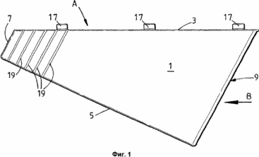
1 is a front view of a first embodiment of a waterproofing element (apron) in accordance with one aspect of the invention.
FIG. 2 is a top view of the apron shown in FIG. 1, viewed in the direction indicated by the arrow A. FIG.
3 is an end view of the apron shown in FIG. 1, when viewed in the direction indicated by arrow B.
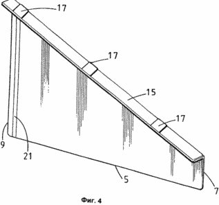
FIG. 4 is a perspective view of the rear side of the apron shown in FIG. 1. FIG.
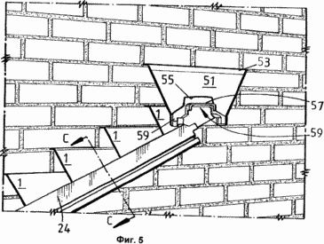
FIG. 5 is a perspective view of a greenhouse roof waterproofing system in which the waterproofing element shown in FIG. 1 is used. FIG.
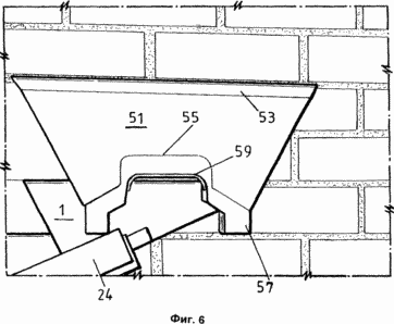
FIG. 6 is a perspective view of the ridge shown in FIG. 5 on a larger scale. FIG.
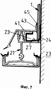
FIG. 7 is a schematic section of section c-c of FIG. 5. FIG.
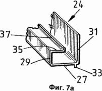
7a is a perspective view of one end of the collar channel shown in FIG. 7. FIG.
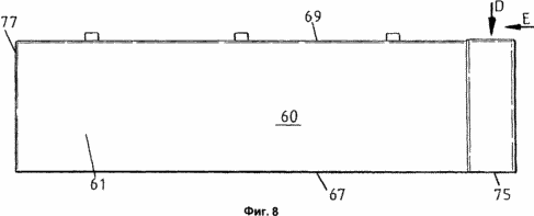
FIG. 8 is a front view of an alternative embodiment of an apron according to the invention. FIG.
FIG. 9 is a plan view of an alternative embodiment of the apron shown in FIG. 8 when viewed in the direction indicated by the arrow D.
FIG. 10 is an end view of an alternative embodiment of the apron shown in FIG. 8, viewed in the direction indicated by the arrow E.
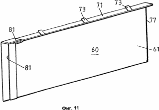
11 is a perspective view of the apron of FIG. 10, viewed from the rear side, from one end and from above.
DISCLOSURE OF THE INVENTION
Various aspects of the present invention are described in terms of its use in greenhouses, however, it is believed that other applications are possible.
First, the first example of practical implementation of the apron is illustrated with reference to FIGS. 1-4. It consists of a body formed of plastic material. The body has an upper end 3, a lower end 5 and opposite ends 7 and 9. The opposite ends in this example are referred to for convenience as the inner end 7 and the outer end 9. In the present example, the opposite ends are substantially parallel. If viewed in the direction of the upper end, the lower ends converge towards the upper ends. In the context of this application, the term internal refers to the end that is closest to the ridge or top of the roof against which waterproofing is applied. The body 1 has an outer surface 11 and a back surface 13. The body 1 is substantially flat. The upper end of the body is provided with a continuous toe 15 that is bent away from the outer surface 11. It is preferable that the toe is positioned at an angle of approximately 90 ° to the plane of the body. This angle may be slightly greater than 90 °, but preferably not less than 90 °. This ensures that water flows from the sock to the side of the body. The toe is equipped with a number of legs 17 located some distance apart along the entire length of the nose. In this exemplary embodiment of the invention, the tabs protrude from the front end of the nose 15 and are inclined backwards, i. E. Toward the outer surface of the body. When using the presser foot, they are used as propping elements, the shape of which can vary, to keep the apron in place, as will be described below. Other configurations can be used that provide the same wedging effect, which prevents the apron from stretching after its installation.
The outer surface of the apron is provided with several grooves 19 spaced from each other and offset from the inner end of the apron. When used, these grooves serve to trap water and prevent it from reaching the inner end of the apron. The back surface of the apron is provided with an elastic sealing element 21 adjacent to the outer end. When used, the outer end of the apron overlaps the inner end of the adjacent apron, wherein the seal contacts the outer surface of the overlapping apron to hold the water passage. As a sealing element, it is convenient to use a compressible foam material.
To provide the roof of the greenhouse with a waterproofing, as shown in FIGS. 5, 6 and 7, a combination of several waterproofing elements, shown in FIGS. 1-4, is used. Aprons are made in the right-hand and left-hand versions to adapt the opposite corners of the roof slope. The aprons shown in FIGS. 1-4 are a right-handed configuration. The left-side configuration is a mirror image of it. Aprons interact with the extruded collar channel 24, as shown in FIGS. 7 and 7a. The glazing beam is shown at number 21 in the position up to the end wall 23. It is provided with an element 25 providing a recess for the collar channel 24. The collar channel 24 has a lower shelf 27 and two vertical walls 29, 31. The bottom shelf 27 has a slope, as seen from the cross-section (Fig. 7), so that water flows to the wall 29 adjacent to the underside. This helps improve drainage. The rib 33 serves to maintain the inclination of the shelf 27 after installation. The upwardly projecting wall 31 has a length greater than the wall 29 from which the shelf 35 extends to partly close the top of the collar channel. At its end, the shelf 35 has a collar 37.
In use, the wall 31 is directly adjacent to the surface of the wall 23. The aprons are located outside of it. After supplying the required amount of mortar, the aprons can be quickly placed in place, starting from the lowest position, moving upwards, towards the top of the roof. The toe 15 of each apron is disposed in a recess in the wall 23, while the lower end is located in the collar channel 24, and as shown in FIG. 5, the outer end of the next abutting apron is applied to the inner end of one apron. The next superimposed apron is positioned so that the grooves 19 are closed. The seal 21 contacts the lower apron and the wall.
7, the glazing beam is equipped with a nozzle 41 that comes into contact with the glazing beam 21 using a tight fit, and has a raised sock with an integrally shaped flexible sealing end 45 adjacent to the aprons to minimize the penetration of water into the collar channel.
At the top of the roof there is a special ridge apron, as seen in FIGS. 5 and 6. It consists of a first section that has a substantially flat body 51 whose upper end 53 is equipped with a toe which is to be placed in the fill of the brickwork. The lower end 55 is cut to accommodate the ridge member 57, which is movable in a vertical direction with respect to the first section. The ridge element includes a recess 59 having a shape allowing the ridge beam or ridge bar of the roof of the greenhouse to be placed (not shown). In the example of practical implementation, the recess has a U-shape. The ridge element is superimposed on the aprons 1, and the body 51 is superimposed on the flat flange 57 of the ridge. Such a design allows the sealing of the ridge without the need for special design of a lead skate apron.
Next, a description will be made with reference to FIGS. 8-11 illustrating an alternative example of an apron that can be used instead of the apron shown in FIGS. 1-4. The alternative can be used in cases where the wall to which the roof is fitted does not have separate rows of brickwork, and instead, for example, a wall with external cement plaster is used where it is possible to form a separate groove in the wall that is practically parallel to the glazing beam and Passing from top to bottom. In fact, such a design can be used for walls with masonry in rows, although this is less traditional.
The apron comprises a number of identical elements 60 formed from plastic and configured so as to provide a mutual butt joint for the purpose of making the apron of the required length. Each apron has a flat body 61 with an outer surface 63 and an inner surface 65, a lower end 67 and an upper end 69. In this example, the body has a rectangular shape. The upper end is provided with a continuous toe 71. The sock is equipped with several special tabs 73. The structure of the toe and legs is a representation of the structure shown in FIG. 1 and is not described in detail hereinafter. The apron has a lower end 75 and an upper end 77. The lower end is clamped at 79 to adhere the upper end of the next adjacent apron. In addition, the crimp provides a recess into which the other end of the adjacent apron enters to provide a sealed connection. To improve the seal, a flexible sealing mastic can be introduced into the recess 81. An alternative example of the practical implementation of the present invention is used in the same manner as shown in FIG. 1 to form a waterproofing system for a glasshouse roof glazing beam, and thus its use is not described below. However, such aprons can also be used for flat roofs.
Both aprons can be used for roofs of other types as an alternative to waterproofing systems using lead or roofing cardboard.
The above aprons and components of the ridge apron are made of plastic of any desired color, but it is assumed that they can be made of metal sheets by pressing. To simulate the traditional appearance of lead roof slabs, gray can be used.
CLAIM
1. A waterproofing system consisting of several aprons in combination with an elongated extruded collar channel equipped with a drainage groove and a vertical wall on which the lower end of the aprons, consisting of molded plastic elements, each having a body with outer and back surfaces, is applied, And with the upper end, the bottom end, the first or upper end and the second or lower end, and with a continuous toe formed along the upper end and directed away from the outer surface of the body.
2. The waterproofing system of claim 1, wherein the sock is equipped with propping means.
3. The waterproofing system according to claim 2, wherein the proppants comprise a plurality of separate elements spaced apart from each other.
4. The waterproofing system according to claim 3, wherein said individual elements, spaced apart from each other, are in the form of tabs.
5. The waterproofing system of claim 4, wherein the legs are deformable.
6. The waterproofing system of claim 5, wherein the tabs protrude from the end of the nose remote from the body.
7. A waterproofing system according to one of claims 4, 5 or 6, in which the legs are directed towards the body in order to provide an end fitting.
8. A waterproofing system according to claim 6 or 7, wherein the tabs are formed on the upper side of the above-mentioned toe.
9. A waterproofing system according to one of claims 4 to 8, wherein the feet and / or sock have a specially treated surface for better setting with a mortar or sealant.
10. A waterproofing system according to one of claims 1 to 9, wherein the upper and lower ends are substantially parallel.
11. The waterproofing system of claim 10, wherein the upper and lower ends are substantially parallel and are arranged at right angles to the upper and lower ends.
12. A waterproofing system according to one of claims 1 to 9, in which the upper and lower ends converge in a direction from the lower end.
13. A waterproofing system according to any one of claims 1 to 12, wherein the inner surface is provided with an elastic sealing element adjacent to the lower end for sealing with an overlapping apron.
14. The waterproofing system of claim 13, wherein the sealing element is an elastic foam strip.
15. A waterproofing system according to any one of claims 1 to 14, wherein the upper end is provided on an outer surface adjacent to the outer end with one or more grooves spaced apart from each other.
16. A waterproofing system as claimed in any one of claims 1 to 11 and 13 to 15, wherein the lower end is provided with a recess for inserting the other end of the adjacent apron.
17. The waterproofing system of claim 16, wherein the lower end is formed with a step to overlap the outer surface of the other end of the adjacent apron.
18. A waterproofing system according to any one of claims 1 to 17 in combination with a glazing beam provided with a recess for the drainage channel.
19. The waterproofing system of claim 18, wherein the glazing beam is provided with a nozzle cooperating with the glazing beam and covering the collar channel.
20. The waterproofing system of claim 19, wherein the nozzle is provided with a vertical collar adjacent to the outer surface of the aprons used.
21. A waterproofing system as claimed in any one of claims 1 to 20, further provided with a ridge apron formed from plastic and provided with a collar at its upper end and receiving portion for receiving the ridge beam.
22. The waterproofing system of claim 21, wherein the ridge apron is made of two sections with the above recess formed in the first section as a projection from the flat flange and a collar formed on the second flat section resting on the above-mentioned flange portion.
23. The waterproofing system of claim 21 or 22, wherein the ridge recess is configured to be vertically adjustable with respect to the ridge apron.
24. A collar channel for a waterproofing system consisting of a link of an elongated extruded channel having a base with oppositely projecting side walls, the first of which, when used, is applied to the lower ends of the aprons, the base being inclined downward from the vertical wall to the opposite wall, Drainage groove.
25. A ridge apron for a waterproofing system molded from plastic, with a toe on its upper end and a receiving section for receiving a ridge roof beam, the ridge apron being made of two sections, the first of which forms a recess projecting from a flat flange, and in the second The flat section, supported by the above flange portion, is provided with a collar.
26. The ridge apron of claim 25, wherein the ridge recess can be vertically adjusted with respect to the ridge apron.
print version
Date of publication 01/21/2007


Comments
When commenting on, remember that the content and tone of your message can hurt the feelings of real people, show respect and tolerance to your interlocutors even if you do not share their opinion, your behavior in the conditions of freedom of expression and anonymity provided by the Internet, changes Not only virtual, but also the real world. All comments are hidden from the index, spam is controlled.