| Start of section
Production, amateur Radio amateurs Aircraft model, rocket-model Useful, entertaining |
Stealth Master
Electronics Physics Technologies Inventions |
Secrets of the cosmos
Secrets of the Earth Secrets of the Ocean Tricks Map of section |
|
| Use of the site materials is allowed subject to the link (for websites - hyperlinks) | |||
Navigation: => |
Home / Patent catalog / Catalog section / Back / |
|
INVENTION
Patent of the Russian Federation RU2286430
![]()
PROFILED VENTILATION SYSTEM FOR CHERRY ROOFS
The name of the inventor: ROTTER Martin J. (US)
The name of the patentee: ROTTER Martin J. (US)
Address for correspondence: 129010, Moscow, ul. B. Spasskaya, 25, p. 3, LLC "Law firm Gorodissky & Partners", Pat. G.B. Yegorova, registration number 513
Date of commencement of the patent: 2003.10.02
The invention relates to the field of construction, namely to a profiled ridge vent channel for tiled roofs, having a vent strip located on each side of the roof ridge. The technical result is the creation of a roof ventilation system. Each ventilation strip includes a ventilation material formed from a nonwoven mat. The upper water barrier is attached to the second surface of at least one of the ventilation lanes and extends over the ridge of the roof. The water-blocking element is attached to the first surface and extends in a direction of inclination upward toward the ridge of the roof. In use, the first vent strip is located on the first side of the ridge roof run and the second vent strip is located on the second side of the ridge roof run. The upper water barriers from the first and second ventilation lanes overlap each other at the ridge run. Preferably, the adhesive is positioned on at least one of the upper barriers from the water so that the two water barriers are connected to each other. Facing roofing tiles, which hide barriers from water, are connected with a ridge run. The ends of the facing roof tiles rest on the parts of the first and second ventilation lanes.
DESCRIPTION OF THE INVENTION
The present invention relates generally to the field of ventilation systems for lofts and roofs. In particular, it refers to the ventilation system of the roof ridge for tiled roofs.
A method for ventilating attics under gable roofs is known, by laying a ventilation duct along the ridge of the roof. And the ventilation ducts are created by an open slot along the roof ridge, essentially along the length of the roof, which creates ventilation of the attic by means of a convective airflow and by suction from a wind blowing across the roof.
Differences between different types of ridge ventilation ducts are often included in the lining structures used on top of the ventilation slot to prevent water flow and pest penetration. Typical types of ridge ventilation ducts and lining structures and features or problems associated with various types are described in US Pat. No. 5,167,579. This patent describes how to solve many of the problems associated with prior ridge ventilation ducts, an improved roof ridge ventilation system using a single mat, Created from randomly oriented synthetic fibers that are connected by means of phenolic or latex binders, and cured by heating to create an air permeable mat with different cells. Facing roof tiles are supported on the mat and nailed directly to the roof through the mat. Unlike other ventilation materials, the distinctive features of the mat described in this patent result in many required physical properties such as high tensile strength, high elastic deformation, the ability to transport in rolls and cut along the length, ease of banding, durability in Conditions of the local environment and the possibility of functioning as a barrier against water and insects. Moreover, it provides the above-mentioned required characteristics in a thin sheet in order to allow the ventilation structure to keep the low profile along the ridge of the roof.
Although the ventilation duct described in this patent has the desired applications in many, mostly flat, roofs, it can not be used together with profiled roofs or with heavy roof tiles. In this description, the expression "heavy roof tiles" means tile tiles made of materials that include slate, terracotta, concrete and clay, but are not limited to them. These tiles are distinguished by their volume and weight, as opposed to lighter roofing tiles made of bitumen, wood, fiberglass, polymers and the like.
Previously known vent structures that are suitable for use with such heavy tile roof tiles have typically included a structure for supporting lining elements that are often heavy ridge tile tiles of the same or similar shape and construction as shingles of roof tiles, for example as described In US Pat. No. 5,326,318. However, the structure of the mounted support of curved sheet metal and porous ventilation material requires shipment at fixed lengths. The cost of manufacturing and shipping this type of ventilation will therefore be high. In addition, if the shingles of tiles and tiles of tiles were "contaminated" when laying with cement, to close the gaps between the overlapping tiles of the tiles, and the gaps between the bottom of the tiles of the tiles and the troughs of the roofing tile roof tiles along the ridge, these gaps Should remain open to ventilation in such previously known systems, will probably be filled with cement in accordance with generally accepted roofing practices, to prevent leaks and therefore block any airflow that was to be ventilated.
The ventilation system for the profile roof skylight for metal roofs has been described in US Pat. No. 5,561,953. This system is intended for use with metal roof panels having a profiled surface and is provided with a profiled ventilation strip coated with a flat lining that is nailed to the roof structure. This does not apply to tiled roofs, in which not only the roof surface is profiled, but also the lining is cylindrical and tiled so that the bottom of the tiles of the tiles do not represent a flat surface, and in which the rain running parallel to the roof ridge can penetrate Between the tiles of the tiles.
It is an object of the present invention to provide a new roof ridge ventilation system that is designed for use with heavy ridge tiles and a method for ventilating such tiled roofs by such a new system. In particular, it is designed for typical tiled roofs in which the tile tiles have a generally semi-circular profile and are stacked in turns, inverted and overlapping the preceding row to form a wavy sequence of ridges and troughs. Tiles of tiles of the same or similar shape are then laid along the ridge and attached to the ridge run so as to block the ventilation slot and give the skate a rounded look.
The present invention provides a profiled ridge ventilation duct for tiled roofs. The ventilation duct contains a vent strip located on each side of the ridge. Each vent strip includes a vent material preferably formed from a nonwoven mat that includes a first surface with such a profile to drive it to the roof tile profile and a second surface. The upper water barrier is attached to the second surface and is located over the ridge of the roof. The water barrier is preferably attached to the first surface and extends in a sloping direction upward. The water barrier includes a curved part that extends towards the second surface. The water barrier follows the profile of the first surface.
In use, the first vent strip is located on the first side of the ridge roof run and the second vent strip is located on the second side of the ridge roof run. Since the ventilation strips are independent of each other, no special arrangement of roof tiles in one line on either side of the ridge is required in one line, and the ventilation strips can be adjusted to accommodate roof tiles of any width. The upper water barriers from the first and second ventilation lanes overlap each other at the ridge run. Preferably, the adhesive is provided on at least one of the upper barriers from the water, so that the two water barriers are connected to each other. Alternatively, a single water barrier is provided that extends from the first vent strip and overlaps the ridge run and contacts the top of the second vent strip. The upper water barriers direct any moisture that passes through the tiles from the tiles, from the ventilation slots through the roof structure.
The lower water-shielding element is preferably J-shaped and flexible, so that these pieces of the tile roof vent strips can be rolled into a roll for shipping. The lower, water-enclosing element prevents moisture from penetrating the ventilation lanes and directs any moisture that can eventually penetrate the ventilation material back to the roof.
The present invention will be described in more detail with reference to the drawings, in which preferred embodiments of the invention are shown.
In the drawings:
 |
 |
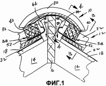
1 is a cross-sectional view through a roof ridge showing a profiled ventilation system for tiled roofs in accordance with a first preferred embodiment of the present invention.
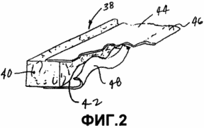
FIG. 2 is a partially exploded perspective view of the ventilation strip used in the profiled tiled roof ventilation system shown in FIG. 1. FIG.
 |
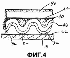 |
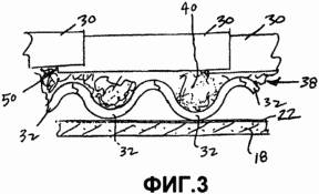
FIG. 3 is a view taken along line 3-3 of FIG. 1. FIG.
FIG. 4 is a view taken along line 4-4 of FIG. 1. FIG.
 |
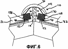 |
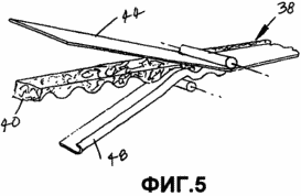
FIG. 5 is a perspective view showing a profiled ventilation strip assembled from profiled ventilation material, an upper barrier from water and a barrier to water.
6 is a cross-sectional view through a roof ridge showing a profiled ventilation system for tiled roofs in accordance with a second preferred embodiment of the present invention.
The description uses only for convenience certain terminology, which is not considered restrictive. Words such as "front", "rear", "top" and "bottom" indicate the directions in the drawings referred to. Terminology includes words specially noted above, derivatives from them and words introduced in this way. In addition, the term "one" ("a" and "one") is defined as including one or more reference items, unless specifically noted.
Preferred embodiments of the present invention will be described with reference to the drawings, wherein like numbers throughout represent such elements.
1 shows a profiled ventilation system 10 for a tiled roof 12. A tiled roof 12 includes a roof structure formed from roof rafters 14 that are connected to a ridge run or beam 16. The cover 18 may be applied over the rafters 14 as shown and the clearance Or the slit 20 remains on each side of the ridge run 16 for ventilating the ridge. Alternatively, the battens or other supporting structures may be used. The ridge run 16 passes over the cover 18 or is ramped up to the desired height so that the roofing tiles 30 for the tiled roof 12 can be attached thereto. Roofing board or other barrier 22 from the water is applied over the cover 18. The roof tiles 32 of the tile are then placed in a position on the roof until the final, uppermost row of the tiles 32 cease at the point below the slits 20.
As shown in FIGS. 1 and 2, the ventilation system 10 comprises venting strips 38 formed of a profiled strip of vent material 40. The ventilation material 40 is preferably a nonwoven synthetic material that has an upper open mesh open surface for air flow therethrough The same time acting as a filter to prevent the penetration of insects and dirt. The material also prevents the penetration of moisture, such as rain-borne rain, while still allowing the flow of air to pass for ventilation of the attic. A preferred material is described in US Pat. No. 5,167,579. However, other suitable cellular materials, whether they are woven or non-woven, can be used. The ventilation material 40 has a first surface 42 that is profiled with a profile complementing the roofing tiles 32 of the tile and a second surface substantially opposite the first surface which is substantially flat. The ventilation material 40 preferably has a thickness that is greater than the depth of the roof tiles 32 of the roof tiles, so that it can be profiled and remain one. The material 40 may be integrally formed, or may be made from a plurality of pieces of material that are connected to each other, for example, by adhesives, cross-linking, anvil with heat, thermal or friction welding, or melting, or any other suitable means. The layers may be made from the same or different materials, at least one layer of material being breathable. The ventilation material 40 is preferably adhered to roofing tiles 32 of the tile by means of an adhesive 52 applied to at least either the vent material 40 or the roofing tiles 32 of the tile.
The upper barrier 44 from the water is attached to the second surface of the vent material 40. The upper barrier 44 from the water is wide enough so that it extends over the ridge run 16 in the established position and at least partially overlaps the second surface of the vent material 40. The upper water barrier is preferably fabricated From a closed cell foam material or polyvinyl chloride or other polymeric sheet material, but can be made of any suitable waterproof material that can be adhered to or adhered to the vent material 40, for example by means of an adhesive, an anvil with heating, cross-linking, welding With solvent or thermal welding, or by any other suitable means. Adhesive material 46 may be applied to one or both sides of the free ends of the upper barriers 44 from water, so that after installation, the upper barriers 44 from the water of the vent strips 38 overlap and can be glued to each other. However, this is not required. As shown in FIG. 1, preferably, the upper barrier 44 from the water has some stiffness and is inclined outward towards the underside of the ridge roof tiles 30.
The water-shielding element 48 is preferably attached to the vent strip 38. The water-shielding element 48 preferably has a J-shape, but may also have a generally L-shape. Preferably, one rack of the water-shielding member is attached to the first profiled surface 42 of the vent material 40 by adhesive, stitching, anvil with heating, heat welding or solvent welding, or by any other suitable attachment means. The water-shielding element 48 is preferably formed of a waterproof polymeric material that has sufficient rigidity to hold the J-shape while at the same time it is possible to roll the vent strip 38 onto the shipping roll.
Preferably, as shown in FIG. 5, the ventilation strip 38 is assembled in a continuous process, the upper water barrier 44 being adhered to the upper surface of the profiled vent 40, and the water-shielding member 48 is adhered in a continuous strip to the profiled bottom surface 42 of the vent material 40.
6, which shows the ventilation system 110 in accordance with a second preferred embodiment of the present invention. In this embodiment, a single water barrier 144 is attached to the first venting strip 138. The water barrier 144 can be attached to the first vent strip 138 by the processes described above with reference to the upper water barriers 44 from the water of the first preferred embodiment. The second vent strip 168 is formed without a water barrier to be placed adjacent to the first vent strip 138 on the opposite side of the ridge run 116. An adhesive 152 is provided for attaching the ventilation strips 138, 168 to roof tiles in a manner similar to that shown in 1 with reference to a first preferred embodiment. In addition, an adhesive 170 is provided for attaching the free end of the barrier 144 from the water to the second vent strip 168 during the installation.
Referring to FIGS. 1, 3 and 4 for mounting in a first preferred embodiment where the ventilation strips 38 are located on the roofing tiles 32 of the roof ridge on each side of the roof ridge. The profiled surface 42 of each strip 38 is aligned with the additional protrusions and recesses of the roofing tiles 32, the upper water barriers 44 overlapping each other over the ridge run 16. The adhesive 52 attaches the ventilation strips 38 to the roof tiles 32 of the tile. Adhesive 52 may include a liquid or semi-solid material applied to at least one of: the ventilation strips 38 and the roofing tiles 32 of the tile during the installation process. Alternatively, the adhesive 52 may include adhesive bands of the type known in the art that are supplied pre-bonded along the profiled surface 42 of each vent strip 38. These adhesive bands preferably include a removable strip which, upon removal, leaves an adhesive such as an acrylic or silicone .
Since the two ventilation strips 38 are not connected to each other, no special arrangement is required in one line of roofing tiles 32 on each side of the ridge. In addition, the gap between the ventilation strips 38 and the ridge run 16 can be adjusted to any width of the tiles 30 as the upper water barriers 44 can overlap each other in a controlled manner. If the adhesive is provided at one or both of the free ends 46 of the upper barriers 44 from the water of the vent strips 38, the upper water barriers 44 are adhered to each other. Then, the roof tiles 30 are installed and are preferably connected to the ridge run 16 by fasteners (not shown).
6 shows a second preferred embodiment wherein the first and second venting strips 138, 168 are attached to the roofing tiles 32 of the tile using the adhesive 152 in a manner identical to that described above with reference to the vent strips 38 of the first preferred embodiment. After the ventilation strips 138, 168 have been properly positioned, the water barrier 144 provided on the first vent strip 138 is attached to the second vent strip 168 by the adhesive 170 during installation. Adhesive 170 may include either a liquid or semi-solid adhesive, or alternatively an adhesive strip of the type described above, applied to at least one of the second vent strip 168 and the water barrier 144. The adhesive strips are preferably permanently attached to the barrier 144 from the water and include a removable strip that is removed immediately before the barrier 144 is attached from the water to the second ventilation strip 168. The tile roof tiles 130 are placed over the attached barrier from the water and are supported by the ventilation strips 138, 168. Ridge roof tiles 130 are preferably flush with the barrier 144 from water, which preferably rests on the ridge run 116, as shown, but alternatively two or more of: the tiles 30, the water barrier 144 and the ridge run 116 can be set by a divided gap From each other. Ridge roof tiles 130 are preferably connected to the ridge run 116 by fasteners (not shown).
As shown in FIGS. 1 and 3, according to the first preferred embodiment, the ventilation material 40 is partially compressed by the tiles of the tiles 30, so that the gaps (indicated as 50) created by the overlapping tiles of the tile 30 are filled. Furthermore, in a preferred embodiment in which the vent material is at least partially formed of a nonwoven synthetic fibrous mat as described, for example, in US Pat. No. 5,167,579, the vent material 40 is preferably heated so that it "rises" or expands , And then calenders to a certain thickness before the profiles are cut out to drive them to the roof profiles. Since material 40 is calendered, it can be somewhat expanded due to the fact that the sun heats the roof after installation in order to additionally fill the gaps 50 to prevent the penetration of insects or dirt. The shingles 131 of the shingles according to the second preferred structural embodiment shown in FIG. 6 do not compress the ventilation material 40. However, alternatively, the roof tiles 131 may be configured to lean on the vent material and at least partially compress it as provided In a first preferred embodiment.
In use, the upper water barriers 44, 144 prevent any moisture that penetrates the seams between the overlapping ridge roof tiles 30, 130 into the roof structure through the slots 20. Any moisture transported by the wind, whose movement accelerates the slope of the roof slope, is stopped by the ventilation Material 40, and if any possible penetration through the ventilation material 40 takes place, the water-shielding element 48 blocks further penetration of moisture and directs the moisture back to the roof. Depending on the thickness (in a direction parallel to the roof surface) and the porosity of the ventilation material 40, it is possible that the water-shielding member 48 can be completely eliminated, as shown in the second preferred embodiment of FIG.
In one preferred embodiment, the vent material has a maximum height of about 3 inches and a minimum height of about 0.5 inches between the first and second surfaces. The upper barrier 44 or 144 from the water extends approximately 6 inches from the upper edge of the vent material 40. The water-shielding member 48 has a height between 0.5 and 1.0 inches. However, different sizes can be used depending on the specific profile of the tiled roof.
While the preferred embodiments of the invention have been described in detail, the invention is not limited to these specific embodiments as described above, but should be considered only as a model. Further modifications and extensions of the present invention may be developed and all such modifications are considered to be within the scope of the present invention as defined in the appended claims.
CLAIM
1. A roof ventilation system for a tiled roof having a roof ridge comprising
The first ventilation strip comprising a first ventilation material and having a first surface complementary to the tiled roof and a second surface;
A second ventilation strip located substantially parallel to the first vent strip on the opposite side of the ridge comprising a second ventilation material and having a first surface complementary to the tiled roof and a second surface; and
At least one upper water barrier connected to at least one of the second surfaces of the first and second vent strips and extending therefrom towards the ridge of the roof.
2. A roof ventilation system according to claim 1, wherein the at least one water barrier comprises a first and a second water barrier attached to the first and second vent strips, respectively, each of the water barriers extending from the respective vent strip towards the Another barrier from water.
3. The roof ventilation system according to claim 2, wherein the free end of at least one of the water barriers rests on the ridge run, forming a roof ridge disposed between the first and second ventilation lanes.
4. The roof ventilation system of claim 3, wherein the first and second water barriers include each free ends that overlap each other.
5. The roof ventilation system of claim 4, wherein the free ends of the first and second water barriers are adhered to each other.
6. The roof ventilation system according to claim 1, further comprising air vent holes disposed on opposite sides of the ridge run forming the roof ridge, the air ventilation holes being located between the first and second ventilation lanes for moving air from the inside of the roof through the openings For air ventilation and through the first and second ventilation materials to the outside of the roof.
7. The roof ventilation system according to claim 1, further comprising at least one roof ridge facing tile placed on a roof ridge, whereby a water barrier is placed between the tile and the first and second ventilation materials.
8. The roof ventilation system of claim 7, wherein the first and second ends of the ridge roof tile are supported by respective portions of the second surfaces of the first and second ventilation materials.
9. A roof ventilation system according to claim 8, wherein the ridge roof tile is connected to a ridge run, forming a roof ridge.
10. The roof ventilation system of claim 1, wherein the at least one water barrier comprises a single water barrier having a first end attached to the first vent strip and a second end in contact with the second vent strip.
11. The roof ventilation system of claim 1, wherein the at least one water barrier comprises a single water barrier, the first end of the single water barrier being attached to the first vent material and the second end of the barrier from water being connected by an adhesive with a second vent material .
12. A roof ventilation system according to claim 11, wherein the water barrier is connected by an adhesive strip having a removable strip, with a second vent material.
13. The roof ventilation system of claim 1, wherein the ventilation materials comprise a non-woven cellular material.
14. The roof ventilation system of claim 13, wherein the nonwoven cellular material is a synthetic fiber web treated with at least one binder.
15. The roof ventilation system according to claim 14, wherein the first and second ventilation materials are subjected to heat treatment for expansion and are calendered for expansion after the installation of ventilation materials.
16. The roof ventilation system according to claim 1, wherein the first and second vent materials include profiling on respective first surfaces for interfacing with a complementary profiling of the tiled roof.
17. The roof ventilation system according to claim 1, wherein at least the first and second ventilation materials or the roof tiles of the tile comprise an adhesive applied thereon to fix the first and second vent strips to the roof tiles of the tile.
18. The roof ventilation system of claim 17, wherein the adhesive is a self-adhesive adhesive strip having a removable substrate that opens a self-adhesive adhesive.
19. The roof ventilation system according to claim 1, wherein at least one of the first and second venting strips comprises a water-shielding element connected thereto at a first end of the water-shielding element that extends along the length of the corresponding vent strip to prevent water penetration .
20. The roof ventilation system of claim 19, wherein the water-shielding element includes a second end having a curved portion for preventing water from penetrating.
21. The roof ventilation system of claim 1, wherein the upper water barrier is at least either polyvinyl chloride or closed cell foam.
22. A method for improved ventilation of a building, comprising the steps of:
A roof is provided having at least one ventilation slot located along the ridge of the roof, the roof having a plurality of conjugated tile tiles laid over the roof,
The first vent line is provided on the roof, the first vent strip including a first surface that corresponds to the conjugate tiles of the tile and a second surface having at least a first upper water barrier attached thereto and extending therethrough, wherein the first vent strip is located in One line, mainly adjacent to the roof ridge, and in which the water barrier at least partially covers the roof ridge; and
A second vent strip is applied to the roof, the second vent strip including a first surface that corresponds to the conjugate tiles of the tile and a second surface in which the second vent strip is arranged in one line, mainly adjacent to the roof ridge, on the opposite side of the first vent strip.
23. The method of claim 22, further comprising connecting the free end of the first barrier from water to the second surface of the second vent strip.
24. The method of claim 23, wherein the step of connecting the free end of the first barrier against water comprises attaching the free end of the barrier from water to the second surface of the second vent strip by means of an adhesive applied to at least a second surface of the second vent strip or to the free end Barrier from water.
25. The method of claim 22, further comprising joining at least one roof ridge tile having first and second ends, with a roof along the ridge of the roof, in which the first and second ends of the ridge tile of the tile are supported on respective portions of the second surfaces First and second ventilation lanes.
26. The method of claim 25, wherein the step of creating the roof includes providing a roof with a ridge run arranged in line with the roof ridge and connected to the roof rafters adjacent to at least one ventilation slot and further comprising a ridge tile With a ridge run.
27. The method of claim 22, wherein the steps of applying the first and second vent strips include the steps of applying the first and second vent strips, at least one of which includes a water-shielding element corresponding to the length of the corresponding first surface and extending along it, and attached To it, each water-shielding element including a curved portion to prevent water from penetrating.
28. The method of claim 22, wherein the step of applying the second vent strip comprises applying a second vent strip having a second upper water barrier attached to and extending from it, wherein the second upper water barrier at least partially overlaps the roof ridge .
29. The method of claim 28, further comprising the step of placing the free ends of the first and second upper barriers from the water in the ridge run forming the roof ridge.
30. The method of claim 29, further comprising the step of attaching the free ends of the first and second upper barriers from water to each other.
31. The method of claim 22, wherein the steps of applying the first and second vent strips comprise applying the adhesive to at least one of the first and second vent strips, or the roof tiles of the tile.
32. The method of claim 22, wherein the steps of applying the first and second vent strips include the steps of applying the first and second vent strips having adhesive strips with removable substrates that open the adhesive upon removal on the respective first surfaces of the first and second vent strips.
print version
Date of publication 01/21/2007


Comments
Commenting on, remember that the content and tone of your message can hurt the feelings of real people, show respect and tolerance to your interlocutors even if you do not share their opinion, your behavior in the conditions of freedom of expression and anonymity provided by the Internet, changes Not only virtual, but also the real world. All comments are hidden from the index, spam is controlled.