| section Home
Production, Amateur Radio amateur Model aircraft, rocket- Useful, entertaining |
Stealth master
Electronics Physics Technologies invention |
space Mystery
Earth Mysteries Secrets of the Ocean Stealth section Map |
|
| Use of material is permitted for reference (for websites - hyperlinks) | |||
Navigation: => |
Home / Products Patents / In the section of the catalog / back / |
|
INVENTION
Russian Federation Patent RU2034204
![]()
SOLAR POWER (OPTIONS)
Name of the inventor: Heruni Paris Misakovich [AM]
The name of the patentee: Heruni Paris Misakovich [AM]
Address for correspondence:
Starting date of the patent: 1992.08.18
The inventive solar plant (SES) of the first embodiment comprises a stationary mirror spherical hub 1, inclined at an angle equal to the latitude of the place and the circuit of power generation, having a primary and secondary coils 3 and a turbine with an electric generator, wherein heat exchangers are installed in the vicinity of the hub kvazifokusa farm 14, rotating around the center of curvature of the concentrator. The contour of the power generation and air is made open, the turbine with an electric generator installed in the top center of the sphere or the support tower 12, on the ground or at the bottom of the tower and the turbine with a heat exchanger connected to a flexible or articulated piping, and an electric generator coupled to the turbine propeller shaft. Fixed spherical hub is made in the form of excerpts from the hemisphere with the aperture angle of 150 degrees. in the local meridian plane. The curved surface or the envelope of the spiral heat exchanger pipe are perpendicular at each point of the reflected rays from the spherical mirror and set parametric equation. At the upper end of a rotating farm installed optical telescope, and at the lower end - receiving antenna - illuminator, allowing spare time (eg at night) used SES as an optical (or) radio telescope. In the second version of the SES with a fully fixed nodes and mobile secondary mirror set profile of the latter.
DESCRIPTION OF THE INVENTION
The invention relates to solar engineering, in particular to the powerful power plants and heating plants.
Known solar [1.2] with a movable spherical mirror concentrator aperture plane which is inclined at an angle equal to the latitude of the place and the contour of the power generation with the heat exchanger mounted in the area kvazifokalnoy spherical mirror rotatable about its center.
However, in these devices consists of a spherical mirror fixed and moving parts, the configuration is not stipulated fixed part and the movable part is a substantial share of the total area of the mirror, which increases the cost and decreases the accuracy and reliability in operation. Furthermore, conventional heat transfer fluids (water-vapor) are used in closed-loop power generation that is bulky (it requires cooling tower) and gives a low efficiency. Applicable movable reflector is accompanied by the use of additional mobile hubs and lenses, and its image is given bulky approximate relations, which is not optimal.
The invention aims to extend the scope and efficiency while simplifying the design and manufacturing technology and operation.
This object is achieved by the fact that in the proposed solar power (SES) comprising fixedly mounted mirror spherical hub, the plane of which the aperture is inclined at an angle equal to the latitude of the place and the circuit power generation having one-base or two primary and secondary heat exchangers are connected sequentially or operating autonomously, and a turbine with an electric generator, wherein the main heat exchanger installed on a farm situated on the support tower (or tripod) has a counterweight and situated in kvazifokalnoy region spherical hub at about half the radius of the sphere to rotate around its center, and a main heat exchanger is designed as a volume of a curved surface or coiled tubing, or in the form of a disk perpendicular to the axis of symmetry, or in the form of a cylindrical tube, and an additional heat exchanger is cylindrical and is located along the axis of the hub of symmetry, between the latter and the main heat exchanger with the possibility of sharing with him rotation, the entire reflecting surface and the entire supporting structure of the spherical hub is made entirely stationary, the contour of power generation performed by air and open type turbine with an electric generator installed in the center of a sphere, or the top support tower, or on the surface of the earth at the bottom of the tower and the turbine is connected to flexible or articulated heat exchanger conduit and an electric generator coupled to the turbine propeller shaft.
Moreover, the fixed spherical hub is in the form of a hemisphere with a cutting angle of the aperture 150 in the equatorial plane and 120 in the local meridian plane.
Furthermore, when the main heat exchanger volume in the form of a curved surface or a coiled tubing, the curved surface or the envelope of coiled tubing made in accordance with the equation 
A 2 l cos ![]() where all the linear value (x, y, l) assigned to the radius of the spherical hub, taken as a unit,
where all the linear value (x, y, l) assigned to the radius of the spherical hub, taken as a unit,
x, y coordinates of the current point of the working surface of the heat exchanger,
l distance from the center of the sphere to the top of the hub profile of the heat exchanger, ![]() the angle between the hub symmetry axis and the radius of the sphere at the point of incidence on the nose of this beam from the sun.
the angle between the hub symmetry axis and the radius of the sphere at the point of incidence on the nose of this beam from the sun.
In addition, at night it further comprises an optical reflector mounted on the upper end of the rotating farm carrier main heat exchanger coaxial with the farm and upwardly along the symmetry axis used aperture of the hub, and a removable receiving antenna irradiator mirror hub mounted on the lower end of the farm and aimed at a mirror concentrator.
Moreover, in the SES comprising fixedly mounted spherical hub, the plane of which the aperture is inclined at an angle equal to the latitude of the place, the secondary mirror having a focal point coincident with the center of curvature of the spherical hub, rotatably around the center hub of curvature and contour of the power generation, the envelope Profile secondary mirror made in accordance with the equation 
where x, y coordinates of the current point forming a working surface of the secondary mirror, related to the radius of the spherical hub, taken as a unit, ![]() the angle between the symmetry axis of the hub and a hub radius of curvature at the point of incidence of the beam current.
the angle between the symmetry axis of the hub and a hub radius of curvature at the point of incidence of the beam current.
Moreover, the spherical working surface of the heat exchanger mounted fixedly in the center of curvature of the spherical hub with its center coinciding with the center hub of curvature is formed as cuttings from the sphere with the plane of the aperture, inclined at an angle equal to the latitude of the place and apertured angles equal to 150 in the plane of the equator and 50 ° to the plane of the local meridian.
The presence of the causal relationships between the set of essential features of the invention and achievable technical result (object of the invention) is primarily in the following.
Spherical hub and its support (carrier) design made completely in the form of fixedly welded metal structures provide easy, reliable and low cost of the entire structure as in the manufacture and in alignment mirrors and continuous operation of SES. This is especially important for high-SES with bulky hubs, where the presence of movable sections concentrator is highly undesirable, since the movement of hundreds of tons of designs require tracks with a strong foundation, wheel systems, gearboxes, motors and so on. In addition, the presence of long (tens of meters or more ) metalwork leads to significant distortions of mirror and reduce its accuracy and efficiency because of the temperature changes during the day and from winter to summer. Thus, this solution makes it possible to realize a thin SES (5.10 kW) and a powerful (5-10 mW or more), i.e. significantly expands the scope of the SES while simplifying and reducing the cost of construction. The virtual absence of deformation increases the accuracy and efficiency of the concentrator, ie, its efficiency.
The configuration is completely stationary concentrator mirror with said apertured angles 150 in the plane of the equator and 120 in the plane of the local meridian is optimal and allows (along with the inclined plane of the aperture at an angle equal to the latitude of the place) to ensure the work of SES for this year, for an average of about 9.5 hours per day.
Perform loop power generation air, the open type, allows to simplify the structure (lack of cooling towers), significantly increase the efficiency and ecological purity ensure complete SES, ie greatly improve efficiency.
Profile Execution (envelope) of the heat exchanger in accordance with the above equation provides normal (perpendicular) at each point from the hub rays fall on the working surface of the heat exchanger, thus increasing its efficiency and effectiveness.
The addition of the optical mirrors (telescope) allows the use of SES at night as a fairly large optical telescope (in the scientific and educational purposes) for observations of celestial objects.
Introduction-feed antenna allows SES at night (and day) time as a radio telescope. These activities increase the overall efficiency and general interest of SES.
Implementation Profile of the secondary mirror in accordance with the above simple equation allows you to select its optimal size and location along the axis of symmetry of the hub, which together with the lack of additional moving mirrors and lenses increases the overall efficiency of the SES.
 |
 |
|
 |
 |
|
 |
 |
 |
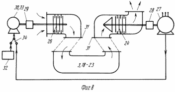 |
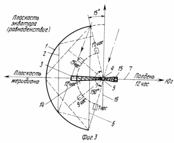
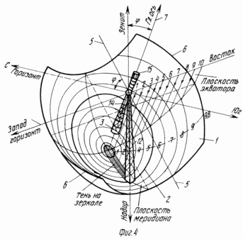
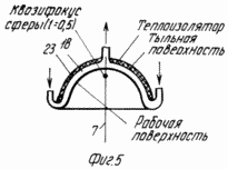
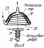
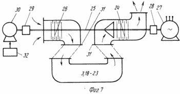
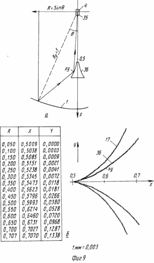
1 shows a diagram of local SES meridian plane; 2 on its structure in the same plane; Figure 3 shows a diagram of SES in the equatorial plane; 4 shows a perspective diagram of a general type SES; Figure 5 shows the basic design of the heat exchanger type of extra-focal volume with the curved surface; 6 combined with the main heat exchanger design extra-focal type of coiled tubing and further as a cylindrical tube; 7 shows a power generation circuit common shaft turbine-compressor; 8 is the same, with separate shafts; 9 SES option of moving the secondary mirror and the fixed coil. SES provides a fixed spherical mirror 1 configured as a clipping from the hemisphere. At any given time of the mirror is used. The diameter of the aperture 2 2 used is selected to be 0.6-0.7 of the diameter of the sphere 1. The position of the aperture used 2 shows (for the afternoon) on the equinoxes (21 March and 22 September), but also the longest day (22 June) and the shortest day of the year (22 December). Accordingly, the position shown the main heat exchanger 3 (the turbine and the electric generator) installed in the hub kvazifokusa spherical, approximately polradiusa scope of mirrors rotatable around the center of the sphere 4. Showing exchanger rotation limits (± 23 ° around the declination axis 16 during the year). Shown hour rotation axis 5 during the day. The plane of the aperture 6 of the truncated hemisphere and the main axis of the mirror 7 are inclined to the south at an angle of <N> phi <N>, equal to the latitude of the place. And shows a hub aperture angle in the plane is equal to 120. The fixed spherical mirror 1 (see FIG. 2) a hub assembled, for example, individual pieces (panels) measuring about 0.5 x 0.5 m 2 of plate glass (coated back reflective metal layer) 6 mm (not beaten deg ), fortified (with the possibility of an initial readjustment) on low racks 8, welded to the welded supporting (bearing) the frame 9 of steel pipe and angles. The frame is fixed to the small concrete foundations 10, arranged on the surface of the earth 11, selected from a natural slope to the south (in order to reduce the amount of frame steel structures 9). Swivel mechanisms (two) with electric drives are installed in the center of the sphere 1 4 on the support tower 12 (height equal to the radius of the sphere and braced by cables), which is a welded metal structure installed on the foundation 13. The mechanisms rotate bascule 14, which is a welded metal bearing at its lower end coil 3, and on the upper end of the counterweight 15. |
|
 | ||
Instead of the counterweight (more accurately, parts thereof) on the upper end of the truss 14 may be an optical mirror is set ( "looking" upwards).
Next to the heat exchanger 3 is installed removable receiving antenna irradiator 17.
Shadow area on the mirror 1 from the heat exchanger 3, the truss 14 and the counterweight 15 (total) is less than 2% of the area of the aperture 2 is used (with respect to the diameter of the latter to the diameter of the sphere, equal to 0.6). The shadow of the tower structure 12 is still about 3%
For washing dust and snow from the mirror 9 in the frame 1 are provided with water pipes and hoses (not shown). Between the panels mirror 1 has the technological gap, serving for water runoff on the ground. The surface of the earth under the mirror is not affected by erosion, as covered with grass or completely concreted.
The rotation of the heat exchanger within 3 hours on the axis 5 in the equatorial plane (in the East-West direction) are shown in Figures 3 and up (with the clippings of the hemisphere) ± 75 ° (10 hours), from 7 am to 17 am solar time, and the aperture angle of the hub in the equatorial plane of about 150.
General view of the fixed spherical mirror 1 in the form of a hemisphere an optimal cutting, but also its location in the space shown in axonometric scheme 4. Cutting surface constructed of 65% of the surface of a hemisphere. It also shows the axis of rotation 5 and 16 14. In the sphere of powerful SES mount rotation mechanisms may not be parallactic and azimuth, that is not difficult. The ratio of the used aperture 2 to the entire surface of the mirror 1 constructed is about 0.31 for the main heat exchanger and increases to 0.41 when the additional heat exchanger.
To reduce the volume of the support frame of metal structures 9 is very important choice SES construction site. As already noted, the choice of a southern slope leads to a substantial reduction of the framework 9 (see FIG. 2).
as it is shown in Figure 4, even better, if that slope is a saddle between two hillocks (canyon ravine oriented to the south). This place is easy to find in the mountains or in the countryside, rugged ravines. Note that at the height of 1500-2000 m altitude solar constant higher than at sea level of about 20% and about 1 kW / m 2. There are usually large number of sunny days per year (270-300).
The main teplobmennik 3 with a concave (the mirror) surface is called extra-focal. His curve is perpendicular to the work surface at each point on the sphere to the reflected beam. Such a surface is described by the equation given. Family can be the main heat exchangers of various types. From the above equations it follows that l ![]() 0.5 have a family of extra-focal coils, and when l> 0,5 prefocal family of heat exchangers (convex to the mirror). Discoid may apply heat exchangers, and a stem (tubular) situated along the symmetry axis 7 of the hub. Can be used, and combinations of these types of heat exchangers. Structurally, the main heat exchangers volume are metal or spiral tube.
0.5 have a family of extra-focal coils, and when l> 0,5 prefocal family of heat exchangers (convex to the mirror). Discoid may apply heat exchangers, and a stem (tubular) situated along the symmetry axis 7 of the hub. Can be used, and combinations of these types of heat exchangers. Structurally, the main heat exchangers volume are metal or spiral tube.
5 shows the basic structure 3 teplobmennika extra-focal volume 18 in the form of a curved surface symmetrical with respect to the symmetry axis 7 and located in the hub area kvazifokalnoy (l 0,5) concentrator. FIG. 6 shows the combined exchanger design with extra-focal primary heat exchanger into a helical pipe 19 from the inside of the envelope 20 in accordance with the above equation and with additional heat exchanger 22 as a cylindrical tube with external circumferential ribs 21, running perpendicular to the rays from the mirror 1. Used for the main heat exchanger 2 Diameter (cm. 1-4) is 0.6 of the diameter of the hemisphere, and for an additional 0.7. This means that an additional heat exchanger provides for about 36% of the heat (if the main power is taken as 100%). The rear (upper) side of the heat exchangers coated with a layer of thermal insulation 23.
Air open loop power generation includes besides 3,18,23 exchanger and an air turbine 24 with the shaft 25, air compressor 26, power generator 27, reduction gears 28, 29, 30 and starter al. (Cm. 7 and 8).
The air turbine 24 is provided with a common shaft 25 with a compressor 25 (see FIG. 7) or without a common shaft (see. Figure 8). In the first case, the turbine 24 is connected to a common shaft 25 with a compressor 26 and an electric generator 27 through the reduction gear 28. To the shaft 25 via a step-up gear 29 and the starter motor 30 is connected, powered by an external power source 31 to the flange 32. The heat exchanger is connected 3,18,23. In the second case (see. Figure 8) turbine 2 (a power generator 27) is mechanically dissociated from the compressor 26 and a (starter), the motor 33 is connected to an electric power cable 27 via the switch 34. In the second embodiment, there are additional (electrical) loss, but the advantage is the possibility of more convenient spatial arrangement of compressor and turbine components, such as reducing the length and bends of pipelines, placing 24 turbines with electric generator 27 (or generator separately) fixed in the center of the sphere 1 or 4 at the base of the tower 14.
As a general assembly of the turbine 24, compressor 26, gears 27 and 29 and the starter 30 can be used in aircraft, helicopter or turbine engines for automobiles. They are very compact, easy to operate at any orientation in space and are available in a large range of capacities from 50 kW to 20 MW or more. Need only a small alteration: to delete the combustion chamber (located between the compressor and turbine) and output air ducts to the flanges 31. These ready-made engines (can be a resource and have served in the air) are best used in mode 0.5 or 0.25 of the nominal power that significantly extend the battery life and dramatically reduce the level of noise emitted by them.
When installing a turbine and electric generator in the center of the sphere, being fixed in the tower or on the ground at the base of the tower, a turbine connected to the heat exchanger flexible or articulated piping, and an electric generator coupled to the turbine propeller shaft.
In the embodiment, the fixed SES exchanger (and the turbine with an electric generator) in the center of the sphere 4 has one additional secondary movable mirror installed at the bottom of truss 14 to rotate around the sphere center. Working (lower) surface of the heat exchanger is in the form of a sphere with its center coincident with the center of curvature of the spherical hub 4. The heat exchanger is small, and the configuration of its surface mirror configuration repeats 1 (see FIG. 4) and is concentric with the latter. Aperture angles of the heat exchanger up to 150 in the equatorial plane and about 50 in a local meridian plane. The generator of the profile of the secondary mirror is given a simple and accurate (not approximate) equation, which simplifies the calculations to facilitate the selection of the optimal version of the SES, increases the accuracy of the position of the secondary mirror and its installation in the space, ie, SES overall efficiency.
SES OPERATES AS FOLLOWS
Every day in the morning 14 (sm.fig.2 and 3) farm axis directed in the sky point where 7 am that day (according to the true solar time) will be the center of the solar disk. With the Sun in this point turns on auto tracking (simple tracking system). After a few minutes, heat exchanger 3 is hot (up to a temperature of about 1200 C) and activated starter 30 (see FIG. 7, 8). Compressor 26 pumps the air from the atmosphere (at a pressure of about 7 atm.) Through a heat exchanger to the turbine 24. 3,18-23 Progrevshis in the boiler to a temperature of about 700-800 ° C, the air turns a turbine, and giving her the energy (heat and pressure) It goes into the atmosphere (at a residual temperature of about 100 ° C). 20 with the starter 30 is turned off and the compressor 26 continues to rotate from the turbine 24 (with a speed of several thousand revolutions per minute). The turbine also (via a reduction gear 28) rotates the electric generator 27 turns the electrical energy to the network. The above temperature, pressure and others depend on the type of turbine. Here are the values for the turbo Mi-8 helicopter with a capacity of 1 MW.
Double-circuit gas turbine efficiency is high and reaches 30-40% of Thus, the efficiency of the SES as a whole approximately equal to: K = K · zert.obm · K · K el.gen pipes. 0.9 · 0.9 · 0.38 · 0.97 · 0.3.
This mode of operation continues for 10 hours a day (from 7 hours to 17 hours) most of the year (about eight months). Reduced duration of the day in winter and depends on the latitude. For example, when ![]() = 40 °, the shortest day of the year, on 22 December, the duration of the day (and the work of the SES) is 9 hours 30 minutes (7 h 15 min to 16 h 45 min). At 7 am the SES starts at 50% capacity from the nominal (7 hours and 15 minutes with 70% of capacity), 8 hours of SES pays already 89% of capacity, and approximately 9 hours 100% Equivalent daily work of SES with 100% capacity is 9.5 hours.
= 40 °, the shortest day of the year, on 22 December, the duration of the day (and the work of the SES) is 9 hours 30 minutes (7 h 15 min to 16 h 45 min). At 7 am the SES starts at 50% capacity from the nominal (7 hours and 15 minutes with 70% of capacity), 8 hours of SES pays already 89% of capacity, and approximately 9 hours 100% Equivalent daily work of SES with 100% capacity is 9.5 hours.
In addition to the SES electrical energy during the same hours in a day 10 generates heat (e.g., steam, hot water) using an additional boiler 22 (see FIG. 6). This additional heat can be, of course, and used to increase the power generated by the SES elektroenepgii (36%).
Using additional boiler and allows for a given power output to reduce SES radius of the sphere 1 at 15% significantly (about 28%) and reduces the mirror surface reduces the amount of materials and construction.
SES work in the version with fixed coil, rotating additional secondary mirror is similar to the above with the only difference being that there is no additional heat exchanger. All the energy used by the selected aperture stationary spherical hub is sent to a heat exchanger in a stationary center of the sphere. Thus, in this embodiment, all units and components (spherical hub, heat exchanger, turbine, electric generator) is completely stationary, but rotates only the secondary mirror.
In their spare time (eg at night), SES can be used as an optical and (or) radio telescope, thanks to the established in the top of the farm 14 optical mirror (telescope) and in the lower part of the receiving antenna irradiators. The latter can be removable or folding (up), not to fall in the afternoon kvazifokus (in case of failure in the drive farm or other emergency) and not deteriorate.
SES simultaneously with the main work can be used and how large and precise solar clock and calendar (in the shadow of the tower), which on a mirror 1 corresponding division should be applied.
CLAIM
1. The solar power plant, comprising a spherical mirror fixedly mounted concentrator aperture plane which is inclined at an angle equal to the latitude of the place and the power generation circuit, having one or two basic primary and secondary heat exchanger connected in series or operating autonomously, and a turbine with an electric generator, with this main heat exchanger installed on a farm situated on the support tower has a counterweight and situated in kvazifokalnoy region spherical hub at about half the radius of the sphere to rotate around its center, and the main heat exchanger is designed as a volume of a curved surface or coiled tubing, or a disk perpendicular to the axis of symmetry, or in the form of a cylindrical tube, and an additional heat exchanger is cylindrical and is located along the axis of the hub of symmetry between the latter and the main heat exchanger with a possibility of joint rotation therewith, characterized in that the contour of the power generation, an air turbine with an electric generator set in the center of the sphere at the top or base of the tower, on the ground or at the bottom of the tower and the turbine with a heat exchanger connected to a flexible or articulated piping, and an electric generator coupled to the turbine propeller shaft.
2. Power plant according to claim 1, characterized in that the fixed spherical hub is in the form of a hemisphere with a cutting angle of aperture plane 150 o and 120 o equator in the local meridian plane.
3. Power plant according to claim 1, characterized in that when the main heat exchanger volume in the form of a curved surface or curved surface of the helical duct coiled tubing or envelope made in accordance with the equation 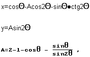
where all linear quantities (x, y, l) referred to the radius of the spherical hub taken to be unity,
x, y coordinates of the current point of the working surface of the heat exchanger;
l distance from the center of the sphere to the top of the hub profile of the heat exchanger;
q the angle between the hub symmetry axis and the radius of the sphere at the point of incidence of this beam at her from the sun.
4. Power plant according to claim 1, characterized in that in the night time, it further comprises an optical reflector mounted on the upper end of the rotating farm carrier main heat exchanger coaxial with the farm and upwardly along the symmetry axis of the aperture of the concentrator is used, and a removable receiving antennu- exciter mounted on the lower end of the farm and directed at mirror concentrator.
5. Solar power plant comprising a spherical hub fixedly mounted, whose aperture plane is inclined at an angle equal to the latitude of the place, the secondary mirror having a focal point coincident with the center of curvature of the spherical hub rotatably mounted around a center of curvature of the hub and the power generation circuit heat exchanger a hub mounted in the center of curvature, characterized in that the envelope of the profile of the secondary mirror made in accordance with the equation 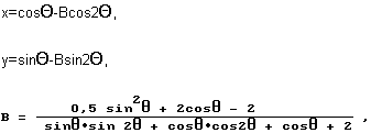
where x, y coordinates of the current point forming a working surface of the secondary mirror, related to the radius of the spherical hub, taken as a unit, ![]() the angle between the symmetry axis of the hub and a hub radius of curvature at the point of incidence of the beam current.
the angle between the symmetry axis of the hub and a hub radius of curvature at the point of incidence of the beam current.
6. The power plant according to claim 5, characterized in that the heat exchanger is fixedly positioned and has a working surface formed as cuttings from a sphere whose center coinciding with the center of curvature of the hub.
print version
Publication date 03.02.2007gg


Comments
Commenting, keep in mind that the content and the tone of your messages can hurt the feelings of real people, show respect and tolerance to his interlocutors, even if you do not share their opinion, your behavior in terms of freedom of speech and anonymity offered by the Internet, is changing not only virtual, but real world. All comments are hidden from the index, spam control.