| section Home
Production, Amateur Radio amateur Model aircraft, rocket- Useful, entertaining |
Stealth master
Electronics Physics Technologies invention |
space Mystery
Earth Mysteries Secrets of the Ocean Stealth section Map |
  |
| Use of material is permitted for reference (for websites - hyperlinks) | |||
Navigation: => |
Home / Products Patents / In the section of the catalog / back / |
|
INVENTION
Russian Federation Patent RU2249721
![]()
wind turbines
Name of the inventor: Cherednichenko Sergey
The name of the patentee: Cherednichenko Sergey
Address for correspondence: 357600, Stavropol Territory, Essentuki, st. Oktyabrskaya, 440, kv.14, SV Cherednichenko
Starting date of the patent: 2003.09.25
The invention relates to wind energy and can be used in the construction of new industrial facilities for fish processing plants for agricultural enterprises on the territory of hospital complexes. The technical result is to increase the coefficient of performance (COP) and expanding the use of wind farms with wind turbines on small plots, not dependent on the strength of wind currents passing through the area. Wind turbines and a fan are combined into one set, setting them in a row on the base, and wherein the fan wind turbines interconnected ducts. Air equipped with flanges for connection, with air ducts, fortified between the wind turbines, are rectangular in shape and between the wind turbine and the fan - tapered. Drum wind turbine wind wheel has curved blades which are attached to the holders and the holders are connected to a horizontal shaft propeller. A horizontal shaft mounted on bearings, connected on one side to the generator and on the other - with coupling (fluid coupling), a pulley which is connected by a belt drive motor pulley. Wind wheel disposed in the cylindrical housing, is displaced from the center of mass of air outlet side, and slits formed in the housing upper part, with its end walls have holes in the central portion. Wind farm is equipped with a distributor, and the blocking of starting the power grid, but also has measurement and control instruments.
DESCRIPTION OF THE INVENTION
The invention relates to wind energy and can be used to generate electricity, but also as a drive to the necessary equipment.
Known wind power plant, in which the wind turbine (patent №2095623) consists of a drum wind wheel with curved blades fixed to a horizontal shaft. Wind wheel is placed in a cylindrical casing with end walls having upper and lower portions and slits on either side, which are pivotally fastened drop shield if necessary. On the one hand on a horizontal shaft and the braking device is reinforced coupling (fluid coupling) and the other side is connected to a horizontal shaft by means of the coupling halves with a generator. Coupling (fluid coupling) is connected via a belt drive to the motor. The horizontal shaft, a cylindrical housing, a generator and a motor fixed to the supporting structure. Wind turbine is equipped with a ballast and an automatic regulation of air flow. Furthermore, it is known that there was ultimately offer a fan wheel comprising a drum with blades fixed on a horizontal shaft mounted on bearings. Drum wheel is placed in a cylindrical housing with an air inlet and outlet openings of air masses (diffuser). The housing is mounted on the supporting structure. There strengthened and the electric motor, which is connected to the drum wheel shaft (Information obtained from the advertising publishing Industrial equipment: "Ventilation, water supply, heat supply", page 8, in 2002, the publishing house Address: Russia, 109428 Moscow, Ryazan prospectus 8a.
Currently, there is a need to expand the use of wind farm sites with wind turbines, which are more closely located to each other in small areas, not dependent on the strength of wind currents, which are in the area.
Implementation of such a technical result can be achieved if manufacture of wind farm devices, creating a wind farm operation in which it would be possible at the same speed of movement of the blades of a wind turbine, regardless of the wind speed in the area. Wind farm, which is composed of two or more wind turbines, it can be used to start the operating position as a centralized energy supply, and on the diesel generator. Wind farm can be used on newly constructed industrial plants, fish processing plants for agricultural enterprises, housing and communal services, in the territory of hospital complexes.
The essence of the proposal is that the wind farm complex consists of wind turbines, each of which includes a drum wind wheel with blades, fortified to the holders, while the holders are connected to a horizontal shaft. Wind wheel is placed in a cylindrical casing with end walls consisting of two parts - a top and bottom, with openings in its upper part. The horizontal shaft of each propeller disposed in the housing offset from the center toward the exit of air masses. The end walls of the housing are arranged openings. The horizontal shaft is mounted on bearings, with one of its ends is connected via an electric coupling halves with and at the other end thereof is strengthened coupling (fluid coupling). The joint consists of a grooved pulley for a belt drive and socket bearing and as a cylindrical drum with windows in which the connection terminals are arranged freely, and the end wall of the drum to the reinforced sleeve part of the bearing hole. The inner wall of the sleeve is fixed to the propeller shaft, and the cylindrical drum includes a pulley groove. In addition, the housing is attached to the pulley cover covering the bearings. Wind turbine provided with a pulley on the motor shaft, which is connected via a belt drive coupling. The cylindrical casing, an electric motor, generator and wind-wheel fastened to the supporting structure of a wind turbine. Moreover, wind farm comprises a fan, which consists of a drum with blades wheels reinforced on a horizontal shaft disposed in a cylindrical casing with a suction inlet and outlet opening for the air mass (diffuser). The horizontal shaft is mounted on bearings and coupled by means of a pulley and a belt drive with an electric motor. A casing drum wheel and a motor mounted on the supporting structure. Fan, wind turbines are installed and fixed to the base in parallel to each other, the slot of the first turbine housing with one hand is connected to a slot of another wind turbine via a duct, and a slot on the other side is connected to a hole for exit of air masses (diffuser) of the fan via a duct . Wind farm is equipped with a distributor of starting and power system, but also has a blocking system with a trunk supply line from the wind farm generators. Wind farm is equipped with a measuring and controlling instruments.
 |
 |
 |
 |
 |
|
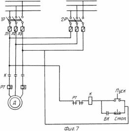 |
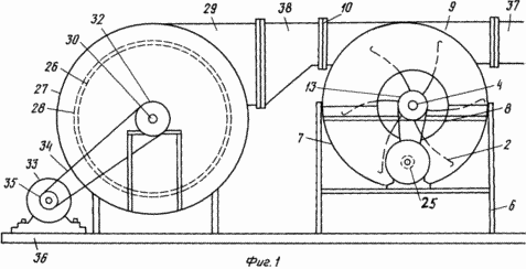
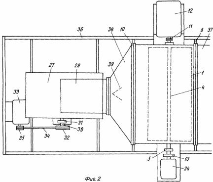
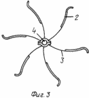
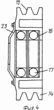
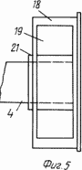
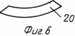
The essence of the invention is illustrated in the drawings, where Figure 1 shows a wind farm that includes wind turbines and a fan mounted on the bottom (side view). 2 shows a wind farm that includes wind turbines and a fan mounted on the base (top view). Figure 3 shows the blades of a wind turbine, fortified to the holders (side view). Figure 4 shows the pulley with reinforced bearings in the nest and the sealing cap (side view). Figure 5 shows a cylindrical drum with the windows mounted on the propeller shaft (a side view). Figure 6 shows the connecting chill (front view). Figure 7 shows a block diagram of an external electric lines and power lines from the wind farm generators, but also start and stop the fan motor. |
|
The apparatus includes a wind farm wind turbines, each of which comprises a drum wind wheel (1), (1, 2) with curved blades (2), reinforced by holders (3) (3), the holders connected to the horizontal shaft (4). Wind wheel (1) mounted on bearings (5) fixed to the supporting structure (6). Wind wheel (1) is arranged in the cylindrical casing (7) consisting of two parts - the upper and lower, and with end walls, which are located in the center hole (8). The top of the housing arranged slots (9) furnished flanges (10) directed in one and the other side. The horizontal shaft (4) at one end thereof is connected via the coupling halves (11) with an electric generator (12). At the other end of the horizontal shaft (4) mounted coupling (fluid coupling) (13) 4. The coupling comprises a pulley (14) with grooves (15) and a socket (16) for the bearings (17) attached to its end wall. Additionally, coupler (13) comprises a cylindrical drum (18), 5, with windows (19), wherein the connecting pads are arranged freely (20), 6. However, the sleeve (21) attached to the end wall of the drum (18) is connected with bearings (17), wherein the inner wall of the sleeve (21) attached to the propeller shaft (4). The very same cylindrical drum (18) located in the groove (22) of the pulley (14). On the pulley body (14) is reinforced by the sealing cap (23). The cavity between the ball bearings filled with viscous lubricants, such NIGROL. Wind turbine is equipped with a motor with reinforced on the pulley shaft (25). The pulley (14) combined with coupling pulley (25) via a belt transmission. Moreover, wind farm includes a fan, consisting of a cylindrical drum (26) with blades arranged in a cylindrical housing (27) with a suction opening (28) and the outlet opening for the air mass (cone) (29). A cylindrical drum (26) mounted on a horizontal shaft (30), which is arranged on the bearings (31), the shaft (30) is connected to a pulley (32). The horizontal shaft (30) is integrated with the motor shaft (33) via a belt transmission (34) of the pulley (32) and pulley (35) located on the motor. Wind turbines and a fan mounted on the base (36) and combined with each other, with slots (9) of wind turbines are connected by flanges (10) ducts (37) which have a rectangular shape. Furthermore, one slot of wind turbines connected to the fan outlet opening for the air mass (cone) (29) by flanges (10) duct (38) which has a conical shape. However, in the duct (38) set the air flow valve (39). He is also the edge of the duct rigidity. Wind farm is equipped with a distributor of starting and control system, and has a blocking system and a trunk with a power line from the wind farm generators. Wind farm is equipped with a measuring and controlling instruments.
Wind farm is used as follows. Determine where to install wind farms and securing the base, you are connecting it to the power supply from the centralized sources of energy (power lines) or from a diesel generator. During start-up wind farm is included in the operating status of the fan. At the same time press the "START", 7, and electrical power phase conductor L 1 passes through the temperature of the RT relay, the coil K, through the closed contacts (at this point) "Start" button, where the meeting with power phase conductor L 3, is created in the coil to the magnetic field under the influence of which the core is pulled together with movable power contact K, as a result of these contacts are closed together with locking pins BC, included with the motor (33). Motor coupled to the drum wheel (26), it unwinds, with the wheel inside the centrifugal force is created that draws air mass through the suction port (22) and pushes them through the diffuser opening (29).
Along with this air mass rush duct (38) through the slot (9) to the blades (2) propeller (1) creating a force for rotation. These air masses rush to another through wind turbine casing slot (7) and through the air duct (37). Meanwhile, the wind wheel (1) rotates and transmits its force through a horizontal shaft (4) electric generator (12), which generates electricity. electric motors (24) are included to create a predetermined desired rotational speed of the electric generator (12). The electric motor, spinning and creating their efforts through a belt drive pulley (14) rotates around its horizontal shaft (4). When rotation of the pulley (14) filled with a viscous lubricant material via sleeve bearings (21) creates additional accelerating horizontal rotation shaft (4). While freely positioned in windows (19) connecting pads (20) due to centrifugal forces generated during rotation is shifted out of windows and connected to one of its walls with the wall of the slot (22), enhancing thus additional soft coupling compound (13) a propeller shaft, whereby the rotational movement is accelerated to the required generator speed (12). During operation of the wind turbine within the drum propeller (1) creates a centrifugal force, whereby the air mass drawn into the hole (8) and then discharged through the curved blades (2) through the slot (9) in the direction of exit of air masses, increasing their speed passing through the duct (33) from one turbine to another. After unwinding generators to the required speed is performed blocking power systems. Disabled when this energy from the power line or diesel generators (1P), 7, and is included on this line use energy generated from the wind farm generators (2P), including on the fan motors and wind turbines, which immediately switched to their work. When the generator rotational speed in excess of the required values, the electric motor (24) or an electric motor (33) of the fan are turned off.
CLAIM
1. Windmill station comprising wind turbines, each of which consists of the wind wheel with curved blades fixed to a horizontal shaft disposed in a cylindrical casing with end walls, made up of two parts - a top and bottom, with the slots, with one end horizontal shaft strengthened coupling (fluid coupling), a pulley which is connected via a belt drive with a pulley of the motor and at the other end of the horizontal shaft is coupled via the coupling halves with a generator mounted on the supporting structure, and provided with a junction and of starting grid, wherein the wind engines, but also fan-attached base, combined with each other, while the slit casing of the first turbine on the one hand coupled with a slot of the second turbine via a duct, and a slot on the other side is connected to a hole for exit of air masses (diffuser) fan and via the duct, the horizontal shaft of each turbine is displaced in a cylindrical casing from the center towards the exit of air masses.
2. The wind farm according to claim 1, wherein the curved blades of the wind wheel mounted to the holders and the holders are connected to the turbine shaft.
3. The wind farm according to claim 1, characterized in that the housing slot formed in the upper portion thereof.
4. The wind farm according to claim 1, characterized in that the end wall of the housing is an opening.
5. The wind farm according to claim 1, characterized in that the power system is equipped with measuring, controlling devices and has a blocking system with a trunk line power from the wind farm.
print version
Publication date 31.01.2007gg
![]()

Comments
Commenting, keep in mind that the content and the tone of your messages can hurt the feelings of real people, show respect and tolerance to his interlocutors, even if you do not share their opinion, your behavior in terms of freedom of speech and anonymity offered by the Internet, is changing not only virtual, but real world. All comments are hidden from the index, spam control.