| section Home
Production, Amateur Radio amateur Model aircraft, rocket- Useful, entertaining |
Stealth master
Electronics Physics Technologies invention |
space Mystery
Earth Mysteries Secrets of the Ocean Stealth section Map |
  |
| Use of material is permitted for reference (for websites - hyperlinks) | |||
Navigation: => |
Home / Products Patents / In the section of the catalog / back / |
|
INVENTION
Russian Federation Patent RU2271464
![]()
Yaw damper windwheels
Name of the inventor: Gabchenko Valery Fedorovich (RU); Lavrov Valery Stepanovich (RU); Porhachev Viktor (RU); Ulanovskii Jacob Benediktovich
The name of the patentee: Limited Liability Company "STROYENGINEERING SM"
Address for correspondence: 141980, Moscow region, Dubna, Str.. Tverskaya, 9, kv.637, VS Lavrov
Starting date of the patent: 2004.04.08
The invention relates to wind energy, and more specifically to a device control, and is intended for damping yaw movement of the head relative to the wind wheel wind turbine towers horizontal-axis type. The technical result is to ensure the necessary quality control orientation to the wind and provide a specified minimum speed yaw propeller. Furthermore, the present invention provides a versatile and reliable construction yaw damper. Yaw damper propeller comprises at least one hydraulic shock-absorber and a device converting rotational movement of the nacelle wind wheel into linear motion of the piston of the hydraulic shock absorber, the hydraulic shock absorber with one end secured to the tower, and communicates with the second conversion device. The best embodiment of the device is its performance as arranged on supporting-swivel gondola zigzag groove disposed therein with a roller connected to the second end of the shock absorber.
DESCRIPTION OF THE INVENTION
The invention relates to wind energy, and more specifically to a device control, and is intended for damping yaw movement of the head relative to the wind wheel wind turbine towers horizontal-axis type.
The problem of damping the yaw propeller (gondola propeller) with respect to the tower of the wind power unit (WPU) arises from the heterogeneity of the wind load - the presence of wind gusts that lead to the yaw propeller relative to the main wind direction, which reduces the characteristics of generated energy, and in some cases may lead damage to the wind turbine.
In the search revealed only a single device of similar purpose - AS USSR №388130, in which the damping is performed by the spring-loaded brake linings. Common to the proposed technical solution is the only purpose of the device.
The disadvantage of the known design is the narrow area of its implementation - for turbines with vindroznym mechanism, and a narrow range of damped load.
The technical problem to be solved by the proposed invention is to provide the necessary quality control orientation to the wind and to ensure a predetermined minimum speed yaw propeller. Furthermore, the present invention provides a versatile and reliable construction yaw damper.
To solve this technical problem yaw damper propeller comprises at least one hydraulic shock-absorber and a device converting rotational movement of the nacelle wind wheel into linear motion of the piston of the hydraulic shock absorber, the hydraulic shock absorber with one end secured to the tower, and communicates with the second conversion device. The best embodiment of the device is its conversion performance as arranged on supporting-swivel gondola zigzag groove disposed therein with a roller connected to the second end of the shock absorber.
conversion device may have another structure, for example, it may be formed as toothed bevel gear one gear crown wheel which is rigidly fixed radially horizontally on a gondola, and the second toothed crown wheel connected to the second damper end fixed perpendicularly to the first to tower rotatable relative to it.
Due to the essential features of the proposed technical solution is achieved by the following technical result - provided sustainability yaw movement during sudden gusts of wind, while providing a predetermined yaw rate, thereby significantly improving transient yawing motion and reduced gyroscopic loads.
As a result, the search for sources of patent and scientific and technological information, a set of attributes that characterizes the proposed yaw damper propeller was not found. Thus, the invention meets the criterion of patentability "new."
Based on a comparative analysis of the proposed technical solution to the prior art on the sources of scientific-technical and patent literature can be argued that between the set of characteristics, including distinctive, and their functions and achievable goals, there is not obvious causal connection. Based on the above it can be concluded that the proposed technical solution in the device should not be explicitly in the art and, therefore, meets the criteria for eligibility "inventive step".
The proposed technical solution can be used in the construction of wind turbines horizontal axial manner with virtually any orientation to the wind, and therefore, this solution meets the criterion "industrial applicability".
The design of the proposed yaw damper propeller illustrated by the drawings Figures 1 and 2.
 |
 |
1 shows a yaw damper propeller design by claim 2.
2 is a yaw damper propeller design by claim 3.
Shown in Figure 1 yaw damper propeller contains at least one hydraulic shock absorber 1 (to ensure the best conditions, there may be several) and a device for converting the rotational movement of the nacelle of the wind wheel in the forward movement of the piston 2 hydraulic shock absorber 1. The hydraulic shock absorber 1 is made, for example car type and comprises a cylinder with hydraulic fluid (not indicated in the drawing) disposed therein a piston 2 with a throttle (not shown in the drawing). converting device is in the form of support located at the 3-swivel propeller nacelle zigzag groove 4. In this hydraulic shock absorber 1 is attached to one end of the tower 5, and communicates with the second conversion device - in this case disposed in the recess through 4 and traction roller 6 7 disposed in the guide 8.
2, the conversion device is located on a slewing gear assembly of the nacelle 3 bevel gear, one conical gear wheel 9 which is rigidly fixed radially horizontally on supporting-swivel nacelle 3 and a second conical gear wheel 10 is fixed perpendicular to the first tower to rotatable with respect to it. In this hydraulic shock absorber 1 is attached to one end of the tower 5, and communicates with the second conversion device - in this case with the second conical toothed wheel 10. While in the tower 5 and on the wheel 10 is pivotally mounted damper 1.
Yaw damper propeller (1) works as follows.
When on the propeller aerodynamic yaw moment head begins to rotate relative to the tower, the groove 4 starts to move relative to the roller 6 which rotates in the groove 4 starts to pull or push in through rod 7 the piston 2 absorber 1 (of course, that the vertical component of the groove 4 is less than values piston overrunning 2). The suspension hydraulic cylinder 2 piston 1 moves in the hydraulic fluid through the throttle made therein. At the same time there is a damper, counteracting yaw moment aerodynamic propeller. Damping torque is a function of the yaw rate. The force created by the hydraulic damper is proportional to the square of the speed of movement in a turbulent flow of hydraulic fluid. Then, the moment created by the damper, is proportional to the square of the yaw rate:
![]()
Where ![]() - Proportionality factor. Let us find a suit of the value of this ratio. Calculations show the yawing motion and experience, to provide yaw rate limit and acceptable performance of yaw transients need to point at the maximum damping yaw rate is equal to the maximum aerodynamic torque at rated wind speed, namely:
- Proportionality factor. Let us find a suit of the value of this ratio. Calculations show the yawing motion and experience, to provide yaw rate limit and acceptable performance of yaw transients need to point at the maximum damping yaw rate is equal to the maximum aerodynamic torque at rated wind speed, namely:
![]()
It is considered that the moments of inertia of the propeller and the nacelle relative to the axis of the tower are small, and the dynamic component J ![]() in this equation can be ignored.
in this equation can be ignored.
The aerodynamic yaw moment is equal to:
where m y - coefficient of aerodynamic yaw moment, in most cases, its value is in the range of 0.08 ... 0.1;
![]() - Air density,
- Air density, ![]() = 1.225 kg / m 3 at standard atmosphere at sea level;
= 1.225 kg / m 3 at standard atmosphere at sea level;
V p - estimated wind speed, ie a wind speed at which the wind wheel goes to the nominal capacity;
R - radius of the wind wheel.
Solving equation (1), (2), (3), we obtain a relation for calculating the coefficient values of required ![]() :
:
Where ![]() - Maximum permissible yaw rate for windwheels propeller with a diameter not exceeding 10 m
- Maximum permissible yaw rate for windwheels propeller with a diameter not exceeding 10 m ![]() For large windwheels diameter greater than 20 m
For large windwheels diameter greater than 20 m ![]() max <0.1 rad / s. Calculated using the formula (4) the value of the coefficient
max <0.1 rad / s. Calculated using the formula (4) the value of the coefficient ![]() It should be ensured through the implementation of the specific design of the yaw damper.
It should be ensured through the implementation of the specific design of the yaw damper.
Yaw damper propeller (2) works on a similar principle. Varies only the design of the device converting rotational motion of the nacelle of the wind wheel in the forward movement of the piston 2 hydraulic shock absorber 1. In this case, the conversion is carried out by means of bevel gear.
Here is an example of calculating the yaw damper for wind turbines with the following parameters:
- Propeller radius R = 2.25 m;
- The estimated wind speed V p = 9.5 m / s;
- The maximum permissible speed of yaw ![]() ;
;
Then needful coefficient ![]() determined:
determined:
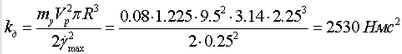
For a given wind turbine device for converting the rotational movement of the nacelle of the wind wheel in the forward movement of the hydraulic damper piston provides the following kinematic relationship a = 28.65 mm / rad (rotation of the gondola at 1 radian is at 28.65 mm movement of the shock absorber rod). Then the velocity V permescheniya piece rod with a maximum yaw rate ![]() is equal to
is equal to
V pc = 28.65-0.25 = 7.16 mm / s
From these relations we find the needs of the shock absorber settings. The maximum force generated by the shock absorber when the velocity of the rod V units, as well:
![]()
Thus the shock absorber when the speed of movement of its rod 7.16 mm / s should create a force 538 kg. From these data, the selection is made of one or more shock absorbers directories.
CLAIM
1. The yaw damper propeller, characterized in that it comprises at least one hydraulic shock-absorber and a device converting rotational movement of the nacelle wind wheel into linear motion of the piston of the hydraulic shock absorber, the hydraulic shock absorber with one end secured to the tower, and communicates with the second conversion device.
2. The damper according to claim 1, characterized in that the conversion device is located on a supporting-swivel gondola zigzag groove disposed therein with a roller connected to the second end of the shock absorber.
3. The damper according to claim 1, characterized in that the conversion device is designed as a conical gear transmission, one bevel gear wheel which is rigidly fixed to the nacelle horizontally radially, and a second bevel gear wheel connected to the second end of the damper, fixed perpendicularly to the first tower rotatable relative thereto.
print version
Publication date 02.02.2007gg
![]()

Comments
Commenting, keep in mind that the content and the tone of your messages can hurt the feelings of real people, show respect and tolerance to his interlocutors, even if you do not share their opinion, your behavior in terms of freedom of speech and anonymity offered by the Internet, is changing not only virtual, but real world. All comments are hidden from the index, spam control.