| section Home
Production, Amateur Radio amateur Model aircraft, rocket- Useful, entertaining |
Stealth master
Electronics Physics Technologies invention |
space Mystery
Earth Mysteries Secrets of the Ocean Stealth section Map |
|
| Use of material is permitted for reference (for websites - hyperlinks) | |||
Navigation: => |
Home / Products Patents / In the section of the catalog / back / |
|
INVENTION
Russian Federation Patent RU2272932
![]()
VANE DEVICE
Name of the inventor: Weinberg Benjamin Y.
The name of the patentee: Weinberg Benjamin Y.
Address for correspondence: 125319, Moscow, ul. Usievicha, 1/5, kv.73, V.Ya.Veynbergu
Starting date of the patent: 2000.12.06
The invention relates to wind energy and can be used in centrifugal devices that convert kinetic wind energy into electric or any other energy. The technical result is to increase the efficiency and improving the design of the device and is provided by the fact that the paddle device containing vanes kinematically associated with an electric power generator, the load electrically connected to the generator, while it is designed as a wind vane to the guide shaft, according to load invention mounted on the moving part of his body, for example, the part which is fixed on a tripod rotatably.
DESCRIPTION OF THE INVENTION
The invention relates to wind energy and can be used in centrifugal devices that convert kinetic wind energy into electric or any other energy.
Known bladed device comprising a blade which is kinematically connected to an electric energy generator, the load electrically connected to the generator, while it is designed as a wind vane to the guide shank (see., E.g., SU, 1787206 A3, cl. F 03 D 1/00 , 01.07.1993) the essential features adopted for the closest analogue of the invention (prototype). The disadvantages of the known devices are low efficiency and low reliability.
The technical result is to increase the coefficient of performance (COP) of the device and improve the design and is provided so that a blade device containing vanes kinematically associated with an electric power generator, the load electrically connected to the generator, while it is designed as a wind vane to the guide shank according to the invention mounted on a load moving part of his body, for example, the part which is fixed on a tripod rotatably.
The load is designed as a light source, such as a light bulb.
The light source is made directional illumination, the illumination is directed to the shank of the blade.
On the shank and blades svetonakopitelnye or light reflecting coating.
At least one light source is mounted on at least one shank.
At least one shank is made in the form of at least one light source electrically connected to the electric power generator.
 |
 |
|
 | ||
 | ||
 |
 |
 |
 |
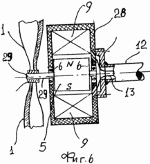
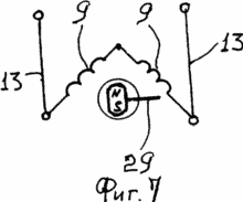
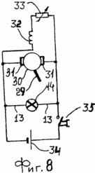
1 is a bladed device (general view) with the load (light bulb) installed on the pipe; Figure 2 illustrates a vane shank with a load device, in the shape of an arrow; 3 shows a shank, which is installed inside the coil filament; 4 shows the shank in a discharge lamp; Figure 5 shows a view A-A of Figure 1; Figure 6 shows reversed generator circuit; 7 is an electrical diagram of the generator; 8 is an electrical diagram of the generator with the shunt. |
|
The device comprises a paddle blade 1 mounted on the holder 2, which is mounted (e.g. pressed into) the housing 3 of the generator of electrical energy, namely its rotor housing 4 which contains permanent magnets 5 (e.g., adhered to). The rotor 4 by bearings 6 mounted on the stator housing 7, which is made winding 8 wound onto the spool 9 with a metal rod to the body of the stator 10. 7 mounted at its center by a flange 11 mounted connector 12 to which it is welded, the coil 9 extend wires 13 that connect the beginning and end of the winding 8 with a light bulb, or other load 14, such as an electric heater, which in the future will not be considered. Housing 15 bulb 14 is mounted on the nozzle 12, for example welded thereto, wherein, the lamp 14 may have a lens 16. At the end of the nozzle 12 is tapered flange 17 and a flattened part provided with holes through which the rivets 12 is secured on the nozzle shank 18 which can be welded to the end of the tube 12. The lamp 14 may be provided with directional illumination, and it can be directed towards the blades, or one side of the shank 18 in that the light reflecting paint svetonakopitelnye or may be coated, but the bulb 14 can be directed to any other way.
The horizontal pipe 12 is mounted on a vertical rod 19, for example welded thereto, and the lower part of the rod 19 is connected through a thrust bearing 20 to the rod 21 with the stand 22 rotatably around its axis. The stem 21 may be welded to a support 22 which is mounted on the body 23 of some device, such as a roof of a building or on the ground.
Bulbs 14 may be mounted directly on the shank 18 and generally be an arrow shape.
A shank guide 18 (guide wing) can be configured as a lamp or bulb-shaped shank of a transparent material such as glass, inside which, in vacuo, installed spiral filament 24 to which the wires 13 are connected.
The shank 18 may be formed as a gas discharge lamp having its shape. In this case, the casing is made of transparent material such as glass, in the interior of which the electrodes 25 and 26, which are connected to wires 13, 27, a starter and a choke (not shown) which can be built into the connector 12.
It can be used facing the generator circuit. On the peripheral portion of its housing 28 are arranged with the windings of the coil 8, 9, which in this example, an anchor, and a rotor 4 provided in this case of the permanent magnets 5 and an inductor which is fixed to the shaft 29, for instance glued thereto. On the shaft 29, outside of the housing 28, the blade set 1 with a holder 2, for example are molded on it. Shaft 29 is mounted on the housing 28 via bearings 6 for rotation about its axis.
The windings 9 may be connected in series.
The vane apparatus may be used various generators, including one whose circuit diagram - shunt. In this example, the armature winding 30 via a brush 31, a collector electrically connected to the excitation winding 32. Subsequently it is established resistance regulating rheostat 33 in the excitation circuit, a lamp parallel to the battery 14 can be set 34, which is attached, for example, a bend 12 and it is installed in series a push button circuit 35. Here, the shaft 29 of the electric generator 3 mechanically connected to the anchor 30 and the through anchor 30 is associated with one blade.
Lobed device operates as follows:
The wind turns the blades 1 which start to rotate inductor, for example, permanent magnets or excitation windings 5 8 which EMF is induced in the windings of the stator 7 which is in this case an anchor. In this case and facing the circuit can be used, in which the stator - inductor and rotor - anchor. In this case the blade 1 is kinematically linked to the anchor. EMF generated by the electric power generator 3, the electric current forms in the load circuit and the lamp 14 lights up, voltage or current limiter can be mounted with the circuit. Battery 34 can be used as the starting point as a current source for the field winding 32, while it is recharged in advance. Can be used complex inducing means, ie a combination of permanent magnets and the excitation windings. Using lamps 14 mounted on the shank 18 or the shank 18 of the execution of a lamp provides a luminous pointer air flow direction, i.e. wind.
In some designs the vane shanks device can be used, which may be implemented as a luminous element of the device, i.e. they made light sources - light bulbs 14.
The movable part paddle device rotates the wind direction changing its direction with the electric power generator and a load, such as a light source - lamp 14.
CLAIM
1. paddle apparatus comprising vanes kinematically associated with an electric power generator, the load electrically connected to the generator, while it is designed as a wind vane to the guide shaft, characterized in that the load mounted on the moving part of his body, for example on the part which is mounted on a tripod rotatably.
2. paddle apparatus according to claim 1, characterized in that the load is made as a light source such as a light bulb.
3. paddle apparatus according to claim 2, characterized in that the light source is directed illumination.
4. paddle apparatus according to claim 3, characterized in that the illumination is directed to the shank.
5. paddle apparatus according to claim 3, characterized in that the illumination is directed to the blade.
6. The vane assembly of any of claims 4 or 5, characterized in that the shank and the blades carried svetonakopitelnye or light reflecting coating.
7. paddle apparatus according to claim 2, characterized in that the at least one light source is mounted on at least one shank.
8. paddle apparatus according to claim 2, characterized in that at least one shank is made in the form of at least one light source electrically connected to the electric power generator.
print version
Publication date 02.02.2007gg


Comments
Commenting, keep in mind that the content and the tone of your messages can hurt the feelings of real people, show respect and tolerance to his interlocutors, even if you do not share their opinion, your behavior in terms of freedom of speech and anonymity offered by the Internet, is changing not only virtual, but real world. All comments are hidden from the index, spam control.