| Start of section
Production, amateur Radio amateurs Aircraft model, rocket-model Useful, entertaining |
Stealth Master
Electronics Physics Technologies Inventions |
Secrets of the cosmos
Secrets of the Earth Secrets of the Ocean Tricks Map of section |
|
| Use of the site materials is allowed subject to the link (for websites - hyperlinks) | |||
Navigation: => |
Home / Patent catalog / Catalog section / Back / |
|
INVENTION
Patent of the Russian Federation RU2276285
![]()
WINDOWS
The name of the inventor: V.Ya. Weinberg
The name of the patentee: OOO "EKOTEHKONSTRUKTSIYA"
Address for correspondence: 125319, Moscow, ul. Usievicha, 1/5, ap. 73, V.Ya. Weinberg
Date of commencement of the patent: 2006.05.10
The invention relates to the field of wind energy. The technical result is to increase the efficiency (efficiency) by improving the design of the blade rotor. The wind farm contains a blade rotor kinematically connected with the load. The vertically disposed rotor blades are mechanically connected to its vertical shaft with the possibility of co-rotating about its vertical axis and at the same time a one-sided deviation from the vertical position, the rotor comprising deflection limiters that allow the rotor blades to rotate only in one direction and determine the direction of rotation of the shaft with blades.
DESCRIPTION OF THE INVENTION
The device relates to converters of wind energy into electrical or mechanical energy and can find wide application in everyday life and industry.
An energy-converting device is known, comprising a rotor blade kinematically connected to a generator shaft (see RU No. 2079703, cl. F 03 D 3/06, 20.05.1997).
The disadvantage of the known device is the low efficiency (efficiency) due to the imperfect design of the blade rotor.
The technical result of increasing the efficiency by improving the design of the blade rotor is ensured by the fact that in a wind turbine comprising a rotor blade kinematically connected to a load according to the invention, vertically disposed rotor blades are mechanically connected to its vertical shaft with the possibility of co-rotating about it Vertical axis and at the same time one-sided deviation of these blades from the vertical position, the rotor comprising deflection limiters that cause the rotor blades to rotate only in one direction and determine the direction of rotation of the shaft with blades. In this case, a part of the blades is mechanically connected to the load shaft, and a part of the blades is mechanically connected to the body of the load itself, which is rotatably mounted, the deflection limiter of the first is made on the opposite side relative to its location in the second, providing rotation of the shaft in the opposite direction to the rotation of the housing Load.
The wind farm is explained by the following drawings:
 |
 |
 |
||
| ||||
 |
 |
|||
 |
 |
|||
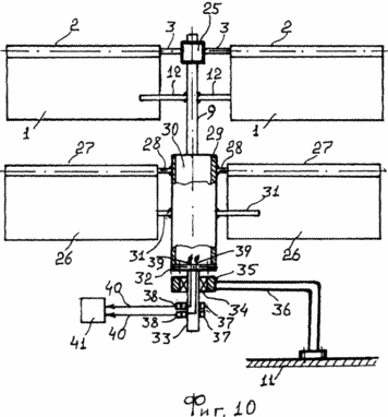 |
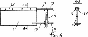
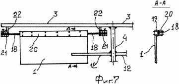
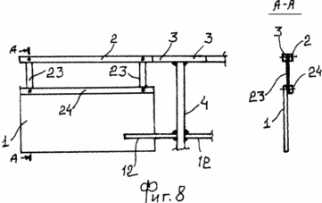
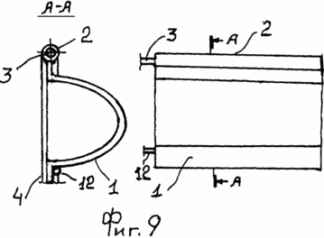
FIG. 1 is a schematic diagram of the device; FIG. 2 shows a fastening assembly; 3 shows a fastening assembly; 4 shows a device (top view); 5 shows an example of the implementation of blades; 6 shows an example of the implementation of blades; 7 shows an example of the implementation of blades; 8 shows an example of the implementation of blades; 9 shows an example of the implementation of blades; 10 shows an exemplary embodiment of the device. |
|||
The device consists of vertically arranged blades 1 fixed with their upper part on sleeves 2, for example welded to them. The sleeves 2 are rotatably mounted on horizontal bars 3 which are mounted on the vertical shaft 4, for example welded to it. The shaft 4 is mounted on the sleeve 5 through the bearing 6, into which it is pressed into the inner ring and which is pressed into the sleeve 5 by its outer ring, the shaft 4 being rotatable about its axis. The sleeve 5 is fixed to the support 7, for example welded to it. The shaft 4 through the gear conical gear 8 is connected to the load shaft 9, for example with the electric generator shaft, or, for example, to the pump shaft, or, for example, to the compressor shaft. The tripod 7 and the load 10 are installed on the base 11, which can be a building site or a vehicle. With one side of the blades 1, which is the same in the direction of rotation, their deflectors 12 are installed in one direction, which can be fixed to the shaft 4 or the rails 3, for example, welded to them, and are a rod or several rods, either in the form of a lattice or other Forms. Above the slats 3, the limiters of the maximum deflection 13 of the blades 1 can be mounted, which can be fastened directly to the rails 3, for example welded to them, or to the shaft 4 and have the shape of a L-shaped rod. The blades 1 fixed to the slats 3, the shaft 4, the limiter of the deflection 12 of the blades 1, the limit limiter 13 are all components of the blade rotor, generally constituting a movable structure or a rotatable structure.
The blades 1 may be of different design, for example, to reduce their weight, they may comprise a film 14 fixed with an interference between the frames 15 and 16, one of which, the frame 15, is fixed, for example welded, to the sleeve 2 (FIG.
The blades 1 can be rigidly fixed to the rail 3, which in cross-section can be rectangular in shape and can be fixed by the bar 17, the blades being made of a flexible spring material, for example fibroblast (FIG. 6).
The blades 1 can be secured by means of a torsion bar 18 made, for example, of a steel spring wire, a steel spring wire or a steel spring rod, wherein the blade 1 is fixed to the bar 19, for example welded to it, to which the bar 20 is connected, Torsion 18. The endings of the torsion bar 18 are fitted with interference in the sleeves 21 and fixed with fixing bolts. The rods 22 are welded to the sleeves 21, the opposite ends of which are welded to the rails 3 (Fig. 7).
The blades 1 can be fixed to the slats 3 by means of flat springs 23, the lower ends of which are fixed to the blades 1 by means of slats 24, i. E. They are clamped between them, and the upper endings are fixed on the rails 3 and by means of the bars 24, i. E. Are sandwiched between them (FIG. 8).
The blades 1 can have different shapes, for example a one-sidedly convex shape, i. E. Have a cross-sectional shape in the form of a half-ellipse, or a cup-like shape, or a generally hemispherical shape (FIG. 9).
The rails 3 can be directly attached to the shaft 9 of the load 10, for example, welded to it, or welded to a hub 25, which is pressed on the shaft 9. We consider this construction for an electric generator. In this case, additional blades 26 are mounted under the blades 1, fixed on the sleeves 27, which are mounted on the rails 28. The rails 28 are fixed to the cage 29 or directly to the casing of the generator 30, for example, they are welded to them. The cage 29 is fixed to the casing of the power generator 30, for example, it is pressed on it. On the cage 29, or on the rails 28, or on the bush 27, limiter deflection 31 blades are installed; Located relative to these blades on the opposite side with respect to their location relative to the respective upper blades 1, which ensures the rotation of the upper blades 1 relative to the direction of rotation of the blades 26 from the same air flow. The cage 29 or the casing of the generator 30 by means of flanges 32 is fixed to the shaft 33, for example, the flanges 32 are welded to it. The shaft 33, through the bearing 34, is rotatably mounted around the axis in the sleeve 35, and the sleeve 35 is fixed to a stand 36, which is mounted on the base 11, similarly to the example of FIG. On the shaft 33, the collector rings 37 mechanically contacting the brushes 38, the rings 37 by the wires 39 through the shaft 33, which can be hollow, can be connected to the electrical output of the generator 30, and the brushes 38 by the wires 40 are connected to a load 41 that can include Yourself battery. In this example, the generator 30, rotatably coupled with the additional blades 26 mechanically coupled thereto, is an integral part of the wind turbine rotor, which is mechanically connected to its shaft by the blades 1. Thus, a part of the blades is mechanically connected to the shaft 9, and a part of the blades Is mechanically connected to the load case 30, for example, to the generator housing 30 (FIG. 10).
The wind turbine works as follows. Under the influence of a wind stream, the direction of which is indicated by arrows, the blade 1, in which the deflection limiter 12 is located on the flow side, starts to rotate with the sleeves 2 around the strips 3, changing the right angle relative to the horizontal line to the sharp one. Vane 1, depending on the strength of the wind, tends to a horizontal position, thus the resistance to air flow from the side of this blade decreases, it seems to flow its flow (Fig. 2). If the deflection limiter 12 is behind the wind direction behind the blade 1, this blade will begin to be pressed by the wind to its deflection limiter 12, which practically does not allow the wind to change its initial vertical position, providing the greatest resistance of this blade 1 to the wind flow (Fig. 3 ). Thus, the wind pressure on the area of the blade 1 in the first case will be less than its pressure on its area in the second case. This can be seen from an example. If the airflow will go from the viewer to the blade located from the viewer to the left, then it will deviate, letting it flow from the same stream, the blade 1, located from the viewer on the right, will be pressed against the deflection limiter 12 located behind it and the blade 1 with slats 3 And shaft 4 will rotate counterclockwise. Thus, the arrangement of the deflection limiters with respect to the blades 1 determines the direction of rotation of the wind turbine rotor.
If the blades 1 are made of a flexible material and rigidly fixed to the slats 3, then they bend from the air flow, passing the air, if the deflection limiter is located before the air flow relative to these blades or if this deflection limiter is located after the blades, then it does not allow them to bend , Then the principle of operation coincides with the previous example.
Similarly, the blades 1 installed on the torsion bar 18 and the springs 23 also work, in the first case they twist the torsion 18 from the wind, deviating if there is no deflection limiter 12 behind them, and in the second case of the blade 1, springs 23 are bent under the influence of the wind and are deflected, Its flow, if there is no flow deflector behind them.
When the blades 1 are one-sidedly convex, the deflection limiter 12 is located on the side of their convexity; in this case, not only the deflection of these blades from the airflow reduces the resistance to it, but the convex, streamlined shape and helps to reduce the resistance to air flow if it is blowing from their side Convexity.
When additional blades 26 are mechanically connected to the load 10, for example with an electric generator 30, which is rotatably mounted on the stand 36, the deflection limiter 12 at the upper blades 1 is located on the opposite side with respect to the position of the deflection limiters 31 at the respective blades 26, which Ensures rotation of the upper blades 1 in the opposite direction with respect to the direction of rotation of the lower blades from the same air flow. Considering that the upper blades 1 are mechanically connected to the load shaft 9, that is, in this case to the generator shaft, and the lower blades 26 are mechanically connected to the load 10, in this case to the generator 30, the shaft 9 and the generator 30 will rotate in opposite directions Relative to each other from the same air flow, which significantly increases the efficiency of the electric generator, the generated electric current of which through the collector transmission of the ring 37-brushes 38 through the wires 40 transfer to the load, for example, lamps or electric heaters.
CLAIM
1. A wind turbine comprising a blade rotor kinematically connected to a load, characterized in that the vertically disposed rotor blades are mechanically connected to its vertical shaft with the possibility of co-rotating about its vertical axis and simultaneously one-sided deflection of these blades from a vertical position, the rotor comprising stops Deviations, which cause the possibility of deflection of the rotor blades only in one direction and determine the direction of rotation of the shaft with blades.
2. Wind power plant according to claim 1, characterized in that a part of the blades is mechanically connected to the load shaft, and a part of the blades is mechanically connected to the body of the load itself, which is rotatably mounted, the deflection limiter of the first ones being executed from the opposite side relative to its location in the second , Ensuring the rotation of the shaft in the opposite direction with respect to the rotation of the load case.
print version
Date of publication 02.02.2007gg


Comments
When commenting on, remember that the content and tone of your message can hurt the feelings of real people, show respect and tolerance to your interlocutors even if you do not share their opinion, your behavior in the conditions of freedom of expression and anonymity provided by the Internet, changes Not only virtual, but also the real world. All comments are hidden from the index, spam is controlled.