| Start of section
Production, amateur Radio amateurs Aircraft model, rocket-model Useful, entertaining |
Stealth Master
Electronics Physics Technologies Inventions |
Secrets of the cosmos
Secrets of the Earth Secrets of the Ocean Tricks Map of section |
|
| Use of the site materials is allowed subject to the link (for websites - hyperlinks) | |||
Navigation: => |
Home / Patent catalog / Catalog section / Back / |
|
INVENTION
Patent of the Russian Federation RU2239091
![]()
WIND GYRLYNAND-HORIZONTAL FLAG-PROPELLER
ROTARY POWER PLANT
The name of the inventor: Georgy Vladimirovich Ginkulov
The name of the patent holder: Ginkulov Georgy Vladimirovich
Address for correspondence: 666534, Irkutsk region., Kazachinsko-Lenskiy rn, pos. Ulkan Str. Sportivnaya, 6-10, G.V. Ginkulov
Date of commencement of the patent: 2003.04.02
The invention relates to wind power, namely to rotary power plants. The technical result consists in increasing the power and efficiency of the power plant, and in simplifying the design of the power plant. The wind turbine-horizontal rotary power plant contains wind turbines, tubular support poles, combined into garlands, an electric generator. Support posts are made of metal, two rotor shafts of wind turbines are connected by a piece of steel cable, the power station contains flags from the shaft, fabric panels, restraints from the elastic web, two adjacent flags located on different sides of the shaft, form an air screw, and garlands of wind turbines are installed either parallel to each other , Or at an angle to each other.
DESCRIPTION OF THE INVENTION
The invention relates to wind power, namely to rotary power plants.
A windmill daisy-horizontal rotary power station is known, containing wind turbines mounted on tubular support poles, united in several straight-horizontal garlands, each rotating only one generator (see, for example, RU 2182257 C2, class F 03 D 3/00, 10.05 .2002), on a set of essential characteristics adopted for the closest analogue of the invention (prototype).
The disadvantages of the known device include the cumbersome design and its high cost, and low reliability.
The technical result, which is to increase the power and efficiency of the power plant, and also to simplify the design of the power plant, is provided by the fact that in a windmill daisy-horizontal rotary power plant containing wind turbines mounted on tubular support poles, combined into several straight-horizontal garlands, each Rotates only one electric generator; according to the invention, the supporting poles are made of metal; two rotor shafts of wind turbines are connected to each other by a piece of steel cable clamped with screws to the inner surfaces of these two shafts, and perpendicular to the surfaces are attached flags, each of which consists of a single pole on which bolts Two fabric cloths at an angle of 90 ° to each other and restraints made of an elastic web supporting the panels at an angle of 90 ° to each other are fixed, all flags are fixed to the shaft so that during the rotation of the shaft, the flags of two adjacent flags are perpendicular to the shaft And perpendicular to each other, and if the angle between the rotor shaft and the direction of the wind is less than 45 °, two adjacent flags located on opposite sides of the shaft form an air screw, and in the locality the garlands of wind turbines are installed either parallel to each other or at an angle to each other Friend.
 | ||
 |
 |
|
 |
 |
|
 | ||
 |
 |
 |
FIG. 1 shows a wind turbine-horizontal rotary power plant with one wind turbine located between the two pillars (general view);
2 shows a flag pair (two flags fixed on different sides of the rotor shaft);
FIG. 3 is a side view of FIG. 2; FIG.
FIG. 4 is a top view of a flag with panels open to the wind at an angle of 90 degrees to each other;
FIG. 5 shows the propeller position of the flags during the horizontal direction of the wind; FIG.
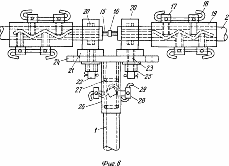
FIG. 6 shows two adjacent rotor shafts mounted on a single support post connected by a cable section; FIG.
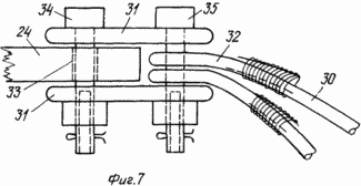
7 - fastening to the bearing area of the upper ends of the braces;
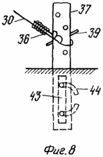
FIG. 8 shows a vertical column of a brace made of larch; FIG.
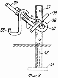
9 shows a column of a brace of metal.
The proposed power plant consists of a large number of wind turbines mounted on supporting poles 1, forming straight-horizontal garlands of windmills, rotating only one, but a powerful quiet-rotating power generator. On each rotor shaft 2 windmills are attached several dozen flags 3, which act as blades in these windmills. Each flag has one shaft 4, to which are attached two panels 5, made of thin strong fabric. All four edges of the panel 5 are reinforced by bending and gluing these edges to the panel 5. They can be glued with "Sprut" glue or the like.
All the rods 4 are fixed perpendicular to the shaft 2, and both panels 5 are fastened to the shaft 4 so that an angle of 90 ° is formed between the planes of these panels 5. Such an angle is maintained between the panels 5 due to the fact that limbs 6 are also superimposed on each of the panels 5, which hold the windings at approximately 10 meters per second, both panels 5 are perpendicular to each other. To fix the panels 5 and the stops 6 to the shaft 4, metal strip strips 7 and bolts 8 are used: two bolts 8 at the top of the shaft 4 and two bolts 8 at the bottom of the shaft 4. A second panel 5 to the same shaft 4 is fastened similarly, but already On its other side at an angle of 90 ° with respect to the first panel 5, with the help of four bolts 8 perpendicular to the four preceding ones, but not touching them, but crossing with them.
Restrictors 6 are cut out (stamped) from an elastic (cord or other) cloth, it is given a sawtooth form with narrow projections and wide depressions. The elasticity of the projections should be such that, with winds up to 10 meters per second, both panels 5 should still be held by the stops 6, keeping an angle of about 90 ° between the panels 5, but already at a wind of more than 10 meters per second and with sharp gusts and limiters 6 and panels 5 should under the pressure of panels 5 on the limiters 6 immediately take a parallel position with the direction of the wind and all panels 5 will immediately relieve themselves of the increased air pressure, protecting this dump from breakage of the details of all windmills of this power plant.
The propeller property of the flags 3 is that if the angle formed between the direction of the wind and the daisy shaft 2 becomes less than 45 °, then one of the panels 5 of each flag 3 will turn by the wind towards the neighboring panel 5 of the same flag 3 and will close with it, forming One blade propeller blade, the second blade is similarly formed, but already on the other side of the daisy bar 2 and the other flag 3. Thus, each pair of flags 3 (flag pair) located on opposite sides of the daisy shaft 2 forms, in this wind direction, one Two-bladed propeller - propeller. And this means that for any direction of the wind the daisy shaft 2 and the power generator will rotate without changing their direction of rotation.
Fastening of the shaft 4 to the rotor shaft 2 is carried out by means of a sleeve 9 and a section of the profile 10 of the U-shape. The sleeve 9 and profile 10 are welded together.
The profile 10 is fastened to the rotor shaft 2 by one bolt 11, and the shaft 4, inserted inside the sleeve 9, is countered by a cotter pin or a piece of wire 12, the ends of which are bent in different directions. On the profile 10 there are still two screws 13, which eliminate the swing of the profile 10 on the rotor shaft 2 by screwing the screws 13 until they come into contact with the shaft 2. The screws 13 are interlocked in pairs by one piece of wire. Similar two screws 14 should be on the sleeve 9 in order to screw them, press the shaft 4 to the inner surface of the sleeve 9 and thereby eliminate the rocking of the shaft 4 relative to the sleeve 9.
Fastening of two adjacent rotor shafts 2 is carried out by means of a piece of an unseen steel cable 15. The diameter of its cross-section must be slightly smaller than the inner diameter of the rotor shaft 2.
The middle of the cable 15 should be labeled 16 (insulating tape) so that the cable 15 is evenly distributed inside these two connecting shafts 2. Now you need to fix this position of the cable 15 with the help of eight power screws 17 located on the shafts 2 above the cable 15. And so that The connection was very high in tensile strength and twisting, it is necessary to screw the screws 17 with great force, giving the rope 15 a zigzag shape inside these shafts 2.
The screwing must begin with the first screws 17 from the end of each shaft 2. The screws 17 are cut by lengths of thick wire 18. If the walls of the connecting shafts 2 are insufficient in thickness for cutting a reliable thread for the screws 17, then on each shaft 2, weld the bushing 19, Which is equal to the outer diameter of the shaft 2.
From the longitudinal displacement, the rotor shafts 2 are held by the thrust bearings 20.
The bearings 20 are connected to the support post 1 in the following manner. To the bottom of each bearing 20, a part consisting of a thrust bearing 21 and a welded thick axis 22 is perpendicularly welded to it. The axle 22 is inserted into the hole 23 formed on the common bearing pad 24 and fixed by the fastening nut 25 from below, that is, under the platform 24. Similarly, This platform 24 and the adjacent bearing 20. Between these two nuts 25 a section of the thick tube-cylinder 26 is welded. The cylinder 26, supported by the support column 1, keeps the bearing pad 24 in a horizontal position.
The welding seam connecting the axle 22 to the thrust bearing 21 is not made from the bottom of the thrust bearing 21, but from above, since the axle 22 is inserted into the hole bored in the middle of the thrust bearing 21, and a wide bevel is made at the upper edge of this hole for the weld that joins the axle 22 with the thrust bearing 21.
On the part of the surface of the support column 1, which is located inside the cylinder 26, two zigzagging rings 27 made of thick wire (10 mm) are welded. The welded seam is made along the entire length of the ring 27, alternating it on one side of the ring 27, then on the other side. The inner diameter of the cylinder 26 should be greater than the outer diameter of the support post 1 by 20 mm. On the cylinder 26, four screws 28 are provided. If all four screws 28 are screwed in until they come into contact (the screwing is carried out gradually, that is, alternately turning one turn for each screw) to the surface of the post 1, then not only the cylinder 26 swings with respect to the post 1, But also the emergency discharge of the cylinder 26 from the post 1, for example, with an upward vortex. The screws 28 are twisted together by pairs of wires 29, and their ends are bent.
If the supporting poles are made from larch, then at the place where the shroud ring 27 is to be located, a 20 mm deep shroud groove must be cut, with the outer diameter of the column 1 being equal to the inner diameter of the cylinder 26.
The support posts 1 are firmly held in the ground, but in spite of this, each pillar 1 must be strengthened by four pullers 30 stretched from the bearing pad 24 of each column 1 in different directions at an angle of 90 ° to each other and relative to the ground at an angle of 45 °.
At the same time, two pullers 30 are tensioned from one side of the daisy-chain shaft 2 and two from the other side. The upper ends of each pair of fasteners 30 are fastened to the bearing pad 24 using two thick rectangular plates 31 which, by means of two bolts, connect the pad 24 and the upper end loops 32 of the two braces 30. Each plate 31 has two bolt holes. Similarly, two other pullers 30 are fastened, but already beyond the opposite edge of this bearing pad 24. The hole 33 near the edge of the platform 24 is intended for a bolt 34 holding both plates 31 behind the pad 24, and the bolt 35 holds the upper end loops of the two braces 30.
The lower end loops 36 of the braces 30 are attached to the vertical bars 37 in the following manner. The loop 36 is tied to a column 37 and two installers pull the loop 36 downward with the help of a metal two-shoulder step 38 in the form of a letter ![]() , In the pull-down position, the loop 36 is fixed by a cylindrical check 39 on the post 37, but already with the help of a third installer, since the first two installers stand on the step 38 on opposite sides of the puller 30, holding the post 37. The check 39 on both sides is put on washers 40, which crash thick cotter pins or thick wire, the ends of which are bent in different directions. To the lower ends of the columns 37, if they are made of metal, thick plates 41 are welded, slightly larger than the diameter of the column 37. Inside the column 37, a peg 42 made of larch should be lowered, and then the column 37 does not rupture when the water in it freezes.
, In the pull-down position, the loop 36 is fixed by a cylindrical check 39 on the post 37, but already with the help of a third installer, since the first two installers stand on the step 38 on opposite sides of the puller 30, holding the post 37. The check 39 on both sides is put on washers 40, which crash thick cotter pins or thick wire, the ends of which are bent in different directions. To the lower ends of the columns 37, if they are made of metal, thick plates 41 are welded, slightly larger than the diameter of the column 37. Inside the column 37, a peg 42 made of larch should be lowered, and then the column 37 does not rupture when the water in it freezes.
The plates 41 are also welded to the lower ends of the support posts 1.
If the columns 37 are made from larch, then two or four larch pegs 44 should be screwed up to the side of the column 37 vertically, as two or four telegraph poles are connected by means of two wire ties with the twist of their crowbar.
CLAIM
A winding daisy-horizontal rotary power station containing wind turbines mounted on tubular support poles combined into several rectilinear horizontal garlands each rotates only one generator, characterized in that the supporting poles are made of metal, the two rotor shafts of the wind turbines are connected to each other by a piece of steel cable, Clamped with screws to the inner surfaces of these two shafts, and flags are attached perpendicular to the surfaces, each of which consists of a single shaft, on which two fabric cloths are fixed with bolts at an angle of 90 ° to each other and constraints made of an elastic web supporting the panels at an angle of 90 ° To each other, all flags are fixed to the shaft so that during the rotation of the shaft the flags of two adjacent flags are perpendicular to the shaft and perpendicular to each other, and if the angle between the rotor shaft and the direction of the wind is less than 45º, then two adjacent flags, Located on different sides of the shaft, form an air screw, and, on the ground, the windmill garlands are installed either parallel to each other or at an angle to each other.
print version
Date of publication 02.02.2007gg


Comments
When commenting on, remember that the content and tone of your message can hurt the feelings of real people, show respect and tolerance to your interlocutors even if you do not share their opinion, your behavior in the conditions of freedom of expression and anonymity provided by the Internet, changes Not only virtual, but also the real world. All comments are hidden from the index, spam is controlled.