| section Home
Production, Amateur Radio amateur Model aircraft, rocket- Useful, entertaining |
Stealth master
Electronics Physics Technologies invention |
space Mystery
Earth Mysteries Secrets of the Ocean Stealth section Map |
|
| Use of material is permitted for reference (for websites - hyperlinks) | |||
Navigation: => |
Home / Products Patents / In the section of the catalog / back / |
|
INVENTION
Russian Federation Patent RU2267028
![]()
Wind power SEGMENT PERFORMANCE
Name of the inventor: Litvinenko AM
The name of the patentee: Voronezh State Technical University
Address for correspondence: 394026, Voronezh, Moscow Avenue, 14, Vilnius Gediminas Technical University, Department of Patent
Starting date of the patent: 2004.07.08
Wind power refers to wind energy and can be used to generate electricity. The technical result consists in enhancing performance through the use of both low-speed and high-speed winds, ensured by the fact that vetroelektrogenerator containing a source of magnetic field, the working coil, yokes and rotor elements - segments mounted on the wind wheel according to the invention the magnetic cores It is in the form of two W-shaped plates arranged in two parallel planes, and in the form of two L-shaped plates which are placed perpendicularly to the W-shaped plates, each L-shaped plate is attached to one of the lateral uprights W-shaped plate.
DESCRIPTION OF THE INVENTION
The invention relates to wind energy and can be used to generate electricity.
Known vetroelektrogenerator containing the tower with rotating propeller, install the device on the wind, and a rotor and a stator with windings [1].
The disadvantage of this device is the increased weight of the rotor, which is to improve performance should have a large number of cavities are rotary elements, which in the case of large diameter windwheels practically unacceptable.
The most close to the claimed the essential features is vetroelektrogenerator [2], containing the tower with rotating propeller, install the device on the wind, rotors and stators with windings, the rotors are in the form of aerodynamic washers and propeller connected flexible elements, which allows for consistent performance each of the two wheels on a stator.
The disadvantage of this device is the ability to work with only one pair of propeller, in the case of wheel-speed leads to unnecessary energy losses at low potential winds, and in the case of slow-moving wheels leads to underutilization in high winds, which generally lowers the operating characteristics of the device.
The technical result consists in improving performance through the use of two pairs of windwheels - horizontal and vertical - is provided by the fact that in the Wind power segment performance, comprising a magnetic field source, working coil, magnetic and rotary elements - segments - installed on the wind wheel, according to invention yokes made in the form of two W-shaped plates arranged in two parallel planes, and in the form of two L-shaped plates which are placed perpendicularly to the W-shaped plates, each L-shaped plate is attached to one of the lateral uprights W-shaped plate .
 |
 |
|
 |
 |
|
 |
 |
|
 |
 |
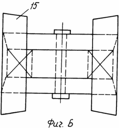
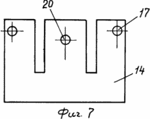
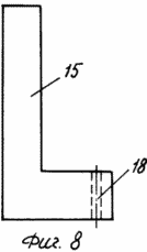
The invention is illustrated by drawings, where Figure 1 is a front perspective view vetroelektrogenerator, Figure 2 - a top view, on a larger scale, the generator stator is illustrated in Figure 3 - a side view, Figure 4 - is a front view of FIG. 5 - a top view, Figure 6 - the rear view, Figure 7 shows a separate W-symmetrical plate-shaped magnetic core 8 - asymmetrical L-shaped plate. |
Wind power segment performance consists of towers 1, windwheels having a rim 2 with ferromagnetic rotor segment elements 3. Propeller-type bicycle spokes have - 4 blades, propeller associated flexible element 5 (for example, a chain or a toothed belt), which covers the pulleys 6, reinforced on hub. In the center, between the vertically mounted propeller and simultaneously between horizontally mounted propeller, mounted stator 7. On the tower is installed turntable 8 and the flexible member is provided with a tensioning device - roller 9 with a spring-loaded lever 10. The rotating base is provided with a tail 11, a transverse cross-arm 12, on the the ends of which bearing units 13 are installed.
Consider the stator unit. It is based on two W-shaped plate 14, arranged in two parallel planes A and B, two L-shaped plates 15, which are arranged perpendicular to the planes A and B. In this case, each of the side struts W-shaped plate is fixed L-shaped plate by bolts 16 passing through holes 17 and 18. The central non-magnetic bolt 19 passed through the holes 20 and the central magnet 21, it pulls the entire structure, including the coil 22, put on the magnet 21.
Operation. Under the influence of the wind flow on the propeller blades 4, and consequently also the wheels 2 come into rotation. Rotor elements 3 alternately come into engagement with the magnetic pole pieces, and in accordance with the principle of the inductor generator commute magnetic flux field sources 2 - permanent magnets made in the form of washers with central holes 19 of non-magnetic bolts.
The technical advantage of this Wind power is the fact that due to the performance of the magnetic circuits in the form of two spatially located W-shaped plates managed to enter into the magnetic interaction is not only a pair of horizontally installed windwheels, but also a pair of vertically mounted windwheels that, in turn, has allowed almost double performance of the generator in comparison with the prototype.
Application of Wind power provides a stable performance, consisting of the fact that the development of stress occurs when the winds of any intensity, as the four-wheel-speed run on one load in turn, that causes a decrease breakaway torque, while maintaining all the main indicators.
INFORMATION SOURCES
1. RF Patent 2184267 - Wind turbine / A.M.Litvinenko, application №2000128442, on 13.11.2000, publ. 27.06.2002, Bull. №18.
2. RF Patent 2211948 - Kontrrotorny vetroelektrogenerator / A.M.Litvinenko, application №2001129415 / 06 dated 31.10.2001, opubl.10.09.2003, Bul. №25.
CLAIM
Vetroelektrogenerator segment performance, comprising a source of magnetic field, the working coil, yokes and rotor elements - segments mounted on the wind wheel, characterized in that the magnetic cores are in the form of two W-shaped plates arranged in two parallel planes, and in the form of two L-shaped plates which are placed perpendicularly to the W-shaped plates, each L-shaped plate is attached to one of the lateral uprights W-shaped plate.
print version
Publication date 02.02.2007gg


Comments
Commenting, keep in mind that the content and the tone of your messages can hurt the feelings of real people, show respect and tolerance to his interlocutors, even if you do not share their opinion, your behavior in terms of freedom of speech and anonymity offered by the Internet, is changing not only virtual, but real world. All comments are hidden from the index, spam control.