
| Start of section
Production, amateur Radio amateurs Aircraft model, rocket-model Useful, entertaining |
Stealth Master
Electronics Physics Technologies Inventions |
Secrets of the cosmos
Secrets of the Earth Secrets of the Ocean Tricks Map of section |
  |
| Use of the site materials is allowed subject to the link (for websites - hyperlinks) | |||
Navigation: => |
Home / Patent catalog / Catalog section / Back / |
|
INVENTION
Patent of the Russian Federation RU2062353
![]()
WIND POWER STATION
The name of the inventor: GI Efimov; Abdurashitov Sh.R.
The name of the patentee: Ufa Research and Design Institute of Industrial Construction
Address for correspondence:
Date of commencement of the patent: 1993.04.28
Use: in wind power, in particular in devices that convert wind energy into electrical energy. SUMMARY OF THE INVENTION: Increasing the power of the windmill by increasing the air flow rate is ensured by the fact that a wind power plant comprising an air flow concentrator in the form of a tent, a wind wheel 8, an electric current generator 9, an inertial energy accumulator 10, with a cylindrical exhaust pipe in the center of the concentrator, Coaxially with it there is a cone with a concave surface. The inner surface of the tent and the outer surface of the cone 4 are interconnected by partitions 5 forming narrowing air channels directed from the periphery to the center and from the bottom upward into a cylindrical exhaust pipe in which the wind wheel 8 is arranged on a vertical shaft 7 transmitting the rotation from the wind wheel 8 to the generator shaft Electric current 9 and inertial energy accumulator 10. On the upper part of the partitions 5 are mounted hinged shutters 12 for closing the air flow. The design of the wind farm allows to increase the area of the gripping flow of air and direct the whole stream to the wind wheel 8 into the exhaust pipe, which will several times increase the flow velocity, and hence the power of the windmill. The power of the windmill can also be increased by supplying the spent hot gas or air streams obtained by burning the utilized fuel to the working cavity of the concentrator.
DESCRIPTION OF THE INVENTION
The invention relates to the field of non-traditional energy sources, in particular to devices that convert wind energy into electrical energy.
The Kolobushkin wind turbine is known (USSR Academy of Sciences N 1211448, class F 03 D 1/04), which contains a tower with windows, inside which there is a rotary vane with a vane fan guiding the wind flow in the windows upwards to the wind wheel. The wind wheel is a combined structure from a horizontal wind wheel with a rim, on which vertical blades are installed, perceiving the air streams that hit the upper windows of the tower. The wind wheel is mounted on a vertical shaft transferring rotation to the shaft of the electric current generator.
The disadvantages of the Kolobushkin windmill include the relative cumbersomeness and complexity of the design as a turning part of the wind turbine and the wind wheel itself, which will significantly reduce the overall efficiency of the electric motor and the annual resource of its operation, since wind at low speeds will not be able to include it in the work.
A wind power unit is known (USSR USSR No. 1307078, cl. F 03 D 1/04) containing a generator, a wind wheel and a wind energy concentrator.
A disadvantage of this invention is that the efficiency of the concentrator is low, since it provides a partial concentration of the air flow. The stream of air passing from the sides and from above the windwheel leaves without working, giving its energy to the unit.
The closest in design to the proposed is the technical solution of the wind turbine (D.de Renzo "Wind Energy", Moscow, 1982 translation from English by VV Zubarev, edited by Ya.I. Shefter, p. 32). The wind turbine is a truncated cone in the form of a tent with raised edges above the ground for free passage of air under the cone in any direction.
In the neck of the cone, a wind wheel is mounted on a vertical shaft, which transmits from the wind wheel the rotation to an electric current generator or an inertial battery (flywheel type). Over the cone there are rotary guide blades for swirling airflow. Part of the free flowing air under the cone rises up into the throat to the wind wheel. Passing through the angled blades, the flow swirls and further sucks air from the cone. In this case, the amount of air flow and its speed increase, which increases the efficiency of the wind turbine.
The drawbacks of the described wind turbine are that the main part of the flow of air, which falls under the raised tent (open freely in all directions), will pass through without giving up its energy. And only part of the flow rises up into the throat to the wind turbines.
The object of the invention is to increase the power of the wind farm by capturing a wide flow of air and concentrating it in a narrow but high-speed flow.
This problem is solved by the fact that in a wind power plant containing an air flow concentrator made in the form of a tent lifted above the ground, a wind wheel with a vertical shaft, an electric current generator and an inertial accumulator, a vertical exhaust pipe is installed on the neck of the concentrator's tent, in the cavity of which one or more Windscreens on vertical shafts kinematically connected to the electric generator shaft and an inertial battery, and a cone with a concave surface is located inside the tent, the inner surface of the tent and the outer surface of the cone connected by vertical baffles forming tapering air channels directed from the periphery of the tent to the center and From the bottom upwards to the vertical exhaust pipe and the blades of the windscreens, and on the upper part of the partitions there are hinged shutters that regulate the amount of air flow to the windrows, and devices for burning gas or for supplying hot air streams are placed in the air channels of the concentrator.
Since the power of the wind farm has a cubic dependence on the speed of the wind blowing the wind wheel (Shefter YI Rozhdestvensky IV "Vetronasovye and wind-electric aggregates", Moscow, 1967), it is more profitable to increase the power of the wind power station by increasing the wind speed, Blowing a wind wheel, than by increasing the diameter of the latter. Theoretically, increasing the wind speed with a concentrator by 4-5 times can give an increase in the power plant's power, respectively, by 64- 125 times compared to a wind turbine having the same diameter of a wind wheel operating at the usual external speed, without the concentration of air flow.
Therefore, in the proposed invention, for the conversion of wind energy to electric energy, a circular tent with raised edges supported on the supports is used, as well as in the known, but, unlike it, the tent on the outside has a vertical exhaust pipe on the neck, and inside the tent there is a cone with Concave surface. The cone and the tent are interconnected by vertical partitions. The partitions form closed, tapering air channels open by a wide part for the entry of the air flow and a narrow part for delivering a tapered and accelerated flow into a vertical exhaust pipe in which wind wheels are mounted on vertical shafts. Thus, all the air flow entering the tent will pass through the exhaust pipe (through the wind wheels), but already with a higher speed than the speed of the outer wind.
 |
 |
 |
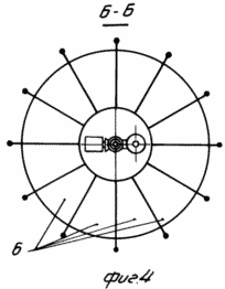 |
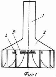
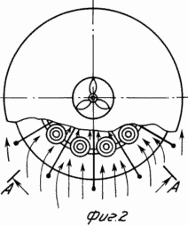
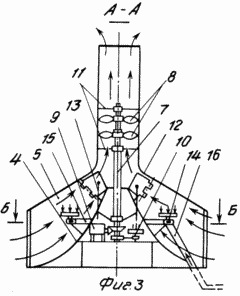
1 shows a general view of a wind farm. FIG. 2 shows a diagram of the concentration of air flows entering the tent. FIG. 3 is a section along AA and shows the direction of the air flow. FIG. FIG. 4 shows a section along the B-B of a cone and vertical baffles. The wind power plant consists of a concentrator having a vertical exhaust pipe 1 and open on the sides of the tent 2 with raised wings resting on the posts 3. The vertical exhaust pipe 1 is installed outside the tent on its neck, and a cone 4 with a concave surface is installed coaxially with it. The inner surface of the tent and the outer surface of the cone are connected together by vertical partitions 5 separating the space between the tent and the cone into channels 6, tapering to the center of the tent and from the bottom upwards. Air from either side of the tent can enter these channels and, squeezing and accelerating, rush into the cavity of the vertical exhaust pipe, inside of which there are mounted on the vertical coaxial shafts (type pipe in the pipe) 7 two wind wheels 8. The inner and outer independently rotating parts of the shaft 7 are kinematically Are connected to the shaft of the electric current generator 9 and the shaft of the inertial accumulator 10 to which the torque from the windscreens 8 is transmitted. The vertical shaft 7 is fixed for stability to the extensions 11 fixed to the wall of the vertical exhaust pipe 1. |
|
In order to prevent breakage of the wind wheel 8 at high speeds of the outer wind and to control the amount of air flow to the wind turbines (maintaining the set power of the installation), the upper part of the partitions 5 are mounted vertically on the hinges of the shutters 12, controlled (by changing the angle of inclination) by means of cables 13. This control can be either manual (winches) or automatic (with the help of sensors from the wind speed in pipe 1 or the rotational speed of the wind wheel 8).
In the ducts 6 there are installed devices 14 for the combustion of the utilized gas. The devices are located on an annular pipe 15 to which gas is supplied through a gas line 16. Through these gas lines and devices, a stream of hot air from the combustion waste incinerators can also be supplied to the ducts 6.
The wind power plant works as follows. Wind flow of any direction, meeting on its way open on all sides of the tent 2, enters through the windows into the channels 6 and, tapering between the vertical partitions 5, the inner surface of the tent 2 and the concave surface of the cone 4, rushes to the center and from the bottom upwards into the cavity of the vertical exhaust Pipe 1. When the air flow is narrowed, the speed of its movement increases several times. The magnitude of the acceleration depends on the ratio of the frontal area of the blown total air flow to the tent 2 and the area of the inner section of the vertical exhaust pipe 1. It is necessary to take into account the loss of the flow velocity from the friction of air particles among themselves, their friction against the channel walls (on the quality of their surfaces) . Then, the accelerated air stream hits the blades of the lower wind wheel 8, rotates it, creating a torque on the shaft 7 (on its outer part), which is kinematically connected to the shaft of the generator 9.
The rotor of the generator receives rotation and begins to produce an electric current for the consumer. Further, the flow of air, giving part of the energy to the lower wind wheel, rushes to the blades of the upper wind wheel 8. The angle of rotation of the planes of the blades of the upper and lower windwheels is regulated depending on the air flow rate and the most optimal operating mode. The torque from the upper wind wheel is transmitted to the shaft 7 (to its internal, independently rotating part) and from it to the shaft of the inertial accumulator 10. But the inner shaft 7 is able to switch to another generator or other mechanism.
To improve the efficiency of the wind (especially in regions with a low average annual rate) and to improve the degree of regulation and stability of the operation of the wind turbines, channels 6 of the tent 2 enter the devices 14 through the gas pipe 16 and the pipe 15, utilizing gas, for example, from oilfields or oil refineries, Which burns in air flows heats it, improves convection and draft in the exhaust pipe 1, and creates better conditions for regulating and maintaining the stability of the wind turbines. If there is no flare gas, but there are biomass wastes in the vicinity of the wind farm (urban landfills, logging waste, farm waste, etc.), it is possible, by burning these waste in furnaces, to feed hot air into the ducts 6 through gas lines 16 and devices 14. In the case of high external wind speeds and the formation of super-permissible hurricane velocities in the flow in the vertical exhaust pipe 1, then to prevent breakage of windscreens and other elements, by tensioning the cables 13, tilt the flaps 12 and part of the stream is cut off, swirled, which reduces its speed . Damper 12 can almost completely block the access of wind to wind turbines (for a period, for example, preventive inspection of the state of the windlass).
The internal location of the cone 4 can be very significant (for example, in the construction of wind power stations with a capacity of 5-6 thousand kilowatts) and can be used not only for locating generators and control devices for the station, but also for any technological equipment for the production of one or the other product Providing sound and heat insulation) and can be performed in two and three floors.
Thus, the proposed design of the wind power plant makes it possible to get rid of the construction of powerful and heavy tower towers to install wind turbines of large diameters (60-80 m and more), the use of special and expensive materials and technologies for manufacturing wind chocks and gondolas for generators, which requires large financial costs. Allows you to be able to regulate the operating modes of the wind turbines, their stability in the operating mode with wide ranges of external wind speeds, allows them to operate at low (wind speed), and the main application of the proposed wind power station with a much smaller (4-5 times) diameter The wind wheel will allow you to obtain a relatively large capacity on the wind turbine.
CLAIM
1. A wind power plant comprising an air flow concentrator in the form of a tent elevated above the ground, a wind wheel with a vertical shaft, an electric current generator and an inertial accumulator, characterized in that at the neck of the hub of the concentrator there is a vertical exhaust pipe in the cavity of which one or more wind turbines are mounted Vertical shafts kinematically connected to the shaft of the electric generator and the inertial accumulator, and inside the tent there is a cone with a concave surface, the inner surface of the tent and the outer surface of the cone connected by vertical partitions forming tapering air channels directed from the periphery of the tent to the center and from the bottom upwards To the vertical exhaust pipe and the blades of the wind turbines, while on the upper part of the partitions there are mounted hinges for regulating the amount of air flowing to the wind turbines.
2. Wind power plant according to claim 1, characterized in that in the air channels of the concentrator there are placed devices for burning gas or supplying hot air streams.
print version
Date of publication 11.01.2007gg
![]()

Comments
Commenting on, remember that the content and tone of your message can hurt the feelings of real people, show respect and tolerance to your interlocutors even if you do not share their opinion, your behavior in the conditions of freedom of expression and anonymity provided by the Internet, changes Not only virtual, but also the real world. All comments are hidden from the index, spam is controlled.