| Start of section
Production, amateur Radio amateurs Aircraft model, rocket-model Useful, entertaining |
Stealth Master
Electronics Physics Technologies Inventions |
Secrets of the cosmos
Secrets of the Earth Secrets of the Ocean Tricks Map of section |
|
| Use of the site materials is allowed subject to the link (for websites - hyperlinks) | |||
Navigation: => |
Home / Patent catalog / Catalog section / Back / |
|
INVENTION
Patent of the Russian Federation RU2249723
![]()
METHOD OF WIND ENERGY TRANSFORMATION AND DEVICE FOR ITS IMPLEMENTATION
The name of the inventor: Nefedov Sergey Ivanovich
The name of the patent owner: Nefedov Sergey Ivanovich
Address for correspondence: 125009, Moscow, PO Box 184, PPF "YUS", Pat. VVKuryanov (for Nefedov SI)
The effective date of the patent: 2003.03.31
The invention relates to the field of wind energy and can be used to convert the energy of air streams into other types of energy, mainly into electrical energy. The technical result is to increase the efficiency of energy conversion. The method includes passing the first incident airflow between two converging and expanding aerodynamic surfaces in order to form a low pressure zone therebetween and passing a second airflow through the pipeline from the surrounding space to the reduced pressure zone. The transducer is placed in the path of the second airflow. In a zone of reduced pressure, at least in one of the aerodynamic surfaces, a cavity is provided to ensure the twisting of the second airflow by the wall of this cavity. Twisting of the second air stream is formed tangentially in the direction of passage of the first incident airflow. The device contains two plates. The pipeline is designed to transfer the second air flow. One end of the pipeline is open and connected to the surrounding space, and the other end is connected to the outer surface of one of the plates. The converter is installed in the pipeline. At least one of the plates is formed with a cavity for twisting the second airflow. The cavity is communicated with the pipeline. The cavity is orthogonal with respect to the direction of the first incident airflow, with the possibility of twisting the second air stream tangentially along the direction of the first incident airflow.
DESCRIPTION OF THE INVENTION
The invention relates to the field of wind energy and can be used to convert the energy of air natural streams into other types of energy, mainly into electrical energy.
Various types of power wind turbines are known which allow the conversion of wind energy into electric power (US 3,883,750); (DE, 2402647); (FR, 2379709).
The limitation of most known devices is a large aerodynamic resistance to air flow, so you have to use a fairly large number of reinforcing elements, various types of supports and stretch marks. When using a large number of simple wind energy converters, to summarize their power it is necessary to occupy vast areas.
A wind power converter is known, comprising two plates made tapering and expanding in the course of the first incident airflow and intended to form in the region of narrowing of the plates a zone of reduced pressure, a conduit for transmitting a second airflow, one end of the pipeline being open and connected to the surrounding Space, and the other end is connected to the aerodynamic surface of the plate in the region of the narrowing of the plates, the converter installed in the pipeline (RU, 2008516).
In this device, the air-receiving element-plate is made in the form of a spatial confuser formed by two hollow spherical segments with a common central axis passing through the vertices of the bulges of the ball segments facing each other. The internal cavities of the spherical segments are communicated by means of channel-posts, which fasten the latter together.
The device is cumbersome, has a sufficiently large aerodynamic drag on the incoming airflow.
The closest technical solution is a system for converting wind energy or another flow, for example water (US 4,079,264), which implements a method for converting the energy of a flow, including passing the first incident airflow between two converging aerodynamic surfaces that expand along it to form A region of narrowing the aerodynamic surfaces of the reduced pressure zone, and transferring a second air stream along the pipeline from the surrounding space to the reduced pressure zone, in the path of which the converter is mounted.
The device for converting wind energy comprises two plates made tapering and expanding in the course of the first incident airflow and intended to form in the region of narrowing of the plates a zone of reduced pressure. The pipeline is designed to transfer the second air flow. One end of the pipeline is open and connected to the surrounding space, and the other end is communicating with the outer aerodynamic surface of one of the plates in the region of the narrowing of the plates. A converter, for example a generator that converts the rotation of the turbine blades into electric power, is installed in the pipeline along the course of the second airflow.
The known device is made in the form of separate cells from interconnected plates. One of the aerodynamic surfaces of the plates of cells is connected by branched sections of the pipeline with the pipeline in which the converter is mounted. Individual cells are located vertically and separated by a free space for the passage of the first incoming airflow both inside the cells and between them. In addition, additional transducers can be used in the device for additional power generation, which are installed in the course of the first oncoming airflow within the cells directly in the zone of reduced pressure between the aerodynamic surfaces of the plates.
The advantage of this technical solution is to provide the possibility of obtaining a sufficiently large total amount of vacuum by using a large number of cells, which makes it possible in addition to increase the output power of the converter.
The limitations of this technical solution are: sufficiently large aerodynamic drag of each cell to the first incoming airflow; Large aerodynamic resistance of the entire structure to the first incoming airflow; Insufficient amount of power generated by the generator relative to the total area of the structure; Large device dimensions and weight.
The problem solved by the invention is to increase the efficiency of energy conversion.
A technical result that can be obtained by carrying out the claimed method is to reduce the aerodynamic drag of each cell by reducing the overall aerodynamic resistance to the first incoming airflow and the second airflow.
The technical result, which can be obtained by performing the device, is a decrease in the aerodynamic resistance of the cell.
An additional technical result that can be obtained by performing the device is to reduce the aerodynamic drag of the entire structure from a multitude of cells to the incoming wind flow; Increase in converter power relative to the area of the structure; Increase in the amount of energy produced by the converter due to the increase in the pressure difference between the inlet of the pipeline and its outlet communicated with the zone of reduced pressure; An increase in the efficiency, and a reduction in overall dimensions of the structure as a whole and a reduction in its weight.
In order to achieve the above object, in a known method for converting wind energy, which includes passing the first incident airflow between two converging aerodynamic surfaces that widen in its course, to form a low pressure zone between them in the region of narrowing of the aerodynamic surfaces, and transfer from the surrounding area to the said reduced Of the second airflow in the path of which the transducer is mounted, according to the invention, a cavity is provided in the reduced pressure zone in at least one aerodynamic surface, allowing the second air flow to curl by the wall of this cavity, whilst twisting the second air flow is tangential in the direction of travel First incoming airflow.
Additional embodiments of the method are possible in which it is expedient that:
- the second air flow in front of the converter was wound in a spiral;
- the second air stream in front of the converter was twisted along the course of the second airflow in the pipeline along a tapering spiral;
- the cavity was performed in a reduced pressure zone in another aerodynamic surface and further the twisting of the second airflow by the wall of this cavity is provided, whilst the twisting of the second air flow is tangent to the direction of the first incident airflow;
- an additional transducer was inserted, which is installed in the course of the first approaching airflow in front of the reduced pressure zone;
- an additional transducer was introduced, which is installed in the course of the oncoming airflow behind the zone of reduced pressure;
- introduced two additional aerodynamic surfaces that are performed by the converging and expanding in the course of the first incident airflow to form a low pressure zone between them, additional aerodynamic surfaces on the sides are closed to the two aerodynamic surfaces to form the cell;
- cavities are provided in each of the four aerodynamic surfaces in which the second airflow is twisted by the walls of these cavities, the twisting of the second airflow in each of the four cavities being tangent in the direction of the first incident airflow;
- several cells are used, the aerodynamic surfaces of the cells are connected to each other in a vertical and / or horizontal row with the formation of neighboring cell cells within the adjacent aerodynamic surfaces; in the course of the second airflow, the pipeline after the converter is branched, and the branched pipeline segments respectively lead, at least, To one of the aerodynamic surfaces of each cell.
In order to achieve the above-mentioned object with the attainment of said technical result in a known wind energy conversion device comprising two plates made tapering and expanding in the course of the first incident airflow and intended to form in the region of narrowing of the plates a zone of reduced pressure, a conduit for transmitting second air Flow, one end of the conduit being open and associated with the surrounding space and the other end communicating with the outer surface of one of the plates in the region of the narrowing of the plates, the converter installed in the conduit according to the invention in the region of the narrowing of the plates, at least one of the plates is provided A cavity for twisting a second airflow that is connected to the pipeline, the cavity is orthogonal with respect to the direction of the first incident airflow, with the possibility of twisting the second air stream tangentially along the direction of the first approaching airflow.
There are additional options for implementing the device, in which it is advisable that:
The cavity was cylindrical or conical in shape and connected with the area of narrowing of the plates through a slot made in the plate;
- a cavity for twisting the second air flow was performed in another plate;
- the open end of the pipeline was provided with an air intake adapted to twist the second air flow relative to the longitudinal axis of the pipeline;
- the air intake was made with an internal conical surface provided with blades mounted at an angle to the longitudinal axis of the air intake or the air intake was made with an internal conical surface in which a helical groove is made;
- an additional converter was introduced, which is installed in front of the zone of reduced pressure or behind the zone of reduced pressure along the course of the first oncoming airflow;
- Two additional plates were introduced, which are made tapering and expanding along the course of the first incident airflow to form a low pressure zone between them, additional plates on the sides are made connected to the two plates to form a cell;
- the cavity was made in each of the four plates;
- several cells were used, the cells are located in a vertical and / or horizontal row, adjacent plates of adjacent cells are connected to form a chamber inside them; during the second airflow, the pipeline after the converter is branched, and the branched ends of the pipeline sections are respectively connected to the outer surface At least one of the plates of each cell;
- the branched ends of the pipeline sections were made of hoses located in the chamber;
- the case of the additional converter was installed in the chamber;
- the first airflow cut-off device, which is made V-shaped and facing its angle towards the first incoming airflow, was inserted, the cut-off device is installed at least along one edge of the outer row of cells, and the air intake is installed in the course of the first incoming airflow behind the cut-off.
These advantages as well as features of the present invention are explained by the best embodiments thereof with reference to the attached figures.
 |
 |
 |
1 schematically shows an apparatus for converting wind energy;
FIG. 2 is a plan view of a lower plate with a cavity; FIG.
FIG. 3 is the same as FIG. 1, with a twist of the second airflow in a spiral; FIG.
 |
 |
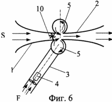 |
FIG. 4 is the same as FIG. 1 with a twist of the second airflow along a tapering spiral; FIG.
FIG. 5 is the same as FIG. 1, when the cavities are formed in both aerodynamic surfaces of the plates; FIG.
FIG. 6 is the same as FIG. 5 with an additional converter installed immediately in front of the reduced pressure zone; FIG.
 |
 |
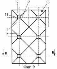 |
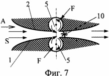
FIG. 7 is a vertical cross-section of a cell of four aerodynamic surfaces with an additional converter installed immediately behind the reduced pressure zone; FIG.
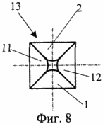
FIG. 8 is a view along arrow A of FIG. 7; FIG.
FIG. 9 is an external view of the cells according to arrow A in FIG. 7, in which the cells are joined end to end into vertical and horizontal rows;
 |
 |
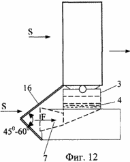 |
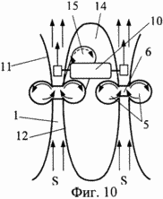
FIG. 10 is a section of BB in FIG. 9, with the additional transducer placed in the closed cavity of adjacent cells similar to FIG. 7; FIG.
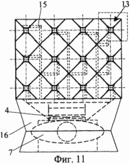
11 shows the appearance of the system from the horizontal and vertical cells towards the first incoming airflow;
FIG. 12 is a side view of FIG. 11; FIG.
 |
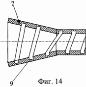 |
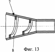
FIG. 13 is a longitudinal cross-sectional view of an air intake, one embodiment;
FIG. 14 is the same as FIG. 13, another embodiment. FIG.
Since the claimed method for converting wind energy is realized when the device is operating, its detailed description is given in the section of the corresponding description of the operation of the device.
The wind power conversion device (FIG. 1) comprises plates 1 and 2 made tapering and expanding in the course of the first approaching air stream S and intended to form in the region of constriction of the plates 1 and 2 of the reduced pressure zone V. The conduit 3 is designed to transmit the second airflow F. One end of the conduit 3 is open and connected to the surrounding space. The other end is connected to the outer surface (aerodynamic surface) of one of the plates, for example, to the aerodynamic surface of the plate 1 in the region of narrowing of the plates 1 and 2. The converter 4 is installed in the conduit 3. In the region of the narrowing of the plates 1 and 2, at least one of the plates , For example a plate 1, is provided with a cavity 5 for twisting the second airflow F. The cavity 5 is communicated with the conduit 3. The cavity 5 is orthogonal to the direction of the first incident airflow S with the possibility of twisting the second airflow F tangentially in the direction of the first incident airflow S .
The cavity 5 is cylindrical (FIG. 1, 2) or conical (not shown in FIGS. 1 and 2) and is associated with the area of narrowing of the plates 1 and 2 through the slit 6 formed in the plate 1.
The open end of the pipeline 3 is provided with an air intake 7 (FIG. 3) adapted to twist the second air flow F relative to the longitudinal axis of the pipeline 3.
The air intake 7 can be provided with an internal conical surface provided with vanes 8 (FIGS. 4, 13) installed at an angle to the longitudinal axis of the air intake 7.
The air intake 7 can be formed with an inner conical surface in which a helical groove 9 is formed (FIG. 14).
The cavity 5 for twisting the second air flow F (FIG. 5) can be made in the other plate 2.
An additional transducer 10 (FIG. 6) can be inserted into the device, which is installed immediately in front of the reduced pressure zone along the first inbound airflow S.
An additional transducer 10 (FIG. 7) can be inserted into the device, which is installed immediately behind the reduced pressure zone along the first inbound airflow S.
Two additional plates 11 and 12 (FIG. 8) can be inserted into the device, which are made tapering and expanding along the first first air stream S to form a low pressure zone therebetween. The additional plates 11 and 12 are made similarly to the aerodynamic surfaces of the plates 1 and 2 (FIG. 1), and are spatially perpendicular to them. On the sides, the additional plates 11 and 12 are connected to the two plates 1 and 2 to form the cell 13 (FIG. 8).
The cavity 5 can be suitably formed in each of the four plates 1, 2, 11, 12 of the cell 13.
Several cells 13 may be used in the system. The identical cells are disposed close to each other in a vertical and / or horizontal row (FIG. 9). The adjacent plates 1, 2, 11, 12 of the neighboring cells 13 are connected to form a chamber 14 inside them (FIG. 10). In the course of the second airflow F, the pipeline 3 after the converter 4 is branched. The branched ends of the segments 15 of the conduit 3 are respectively connected to at least one of the aerodynamic surfaces of the plates 1 or 2 or 11 or 12 of each cell 13 (in FIG. 10, the branched ends of the segments 15 of the pipeline 3 are shown by dashed lines brought to the narrowing of the plates 1 or 2 or 11 or 12 of each cell 13).
The branched ends of the pipeline segments 15 can be made of hoses (flexible), cylindrical or conical in the chambers 14 of the cells 13.
The body of the additional transducer 10 (FIG. 10) can be installed in the chamber 14 for each or some of the cells 13.
A shut-off device 16 of the first oncoming airflow S can be introduced into the system (FIG. 11, 12). The baffle 16 is made V-shaped and facing its angle towards the first incoming airflow S. The baffle 16 is installed at least along one extreme row of the cells 13, for example immediately below them. The air intake 7 is installed in the course of the first oncoming airflow S behind the shut-off 16.
The device (FIG. 1) operates as follows.
The first incident airflow S passes between two aerodynamic surfaces of the plates 1 and 2 that expand and expand in its course to form between them in the region of narrowing of the aerodynamic surfaces of the reduced pressure zone V. The second air flow F is transferred via line 3 to the reduced pressure zone V. A transducer 4 is mounted on the path of the second air flow F. In the reduced pressure zone V, at least one of the plates 1, a cavity 5 is provided to rotate the second airflow F by the wall of this cavity 5. The twisting of the second airflow F is formed tangentially along the direction Passing the first incoming air stream S.
Twisting of the second air flow F can be accomplished by various means. Without introducing any additional elements through the passage of the second air flow F through the conduit 3 and entering it into the cavity 5 (like a rotating funnel formed by draining water from the container through the outlet). The twisting of the second airflow F can be effected directly by rotating the rotor blades of the turbine of the converter 4. Due to the spiral arrangement of the various elements, for example, the blades within the pipeline 3 (Figs. 3, 4, 13) or within the duct 3 of the helical groove (Fig. 14) , Or the corresponding elements in the air intake 7 (FIGS. 3, 4, 13, 14). The cavity 5 can be made cylindrical (FIG. 1, 2) or conical (not shown in FIGS. 1 and 2) and is associated with the area of narrowing of the plates 1 and 2 through a slot 6 formed in the plate 1. The conical shaped cavity 5 is expediently used , When the cavities 5 of the plates 1 and 2 are closed to each other.
The first approaching air stream S (FIG. 1), falling on the narrowing aerodynamic surfaces of the plates 1 and 2, increases the speed of movement, which is maximum in the reduced pressure zone V, especially in the boundary layer. Zone V is supplied via conduit 3 with ambient air spiraling tangentially to the direction of movement of the first approaching air stream S. Unlike analogs in which the second air flow F is supplied orthogonally to the first airflow S, which increases the overall aerodynamic drag at Interaction of these streams, in the claimed method, when the second air flow F is twisted tangentially in the direction of passage of the first approaching air stream S, the directions of the streams incident on the zone V coincide and the resultant stream leaving the zone V flows. In zone V, an effective suction of the second airflow F takes place with a decrease in aerodynamic drag. This makes it possible to significantly reduce the aerodynamic resistance of the plant in comparison with analogues.
Since the second air flow F with low resistance is fed through a separate pipeline 3 from the environment (from the atmospheric pressure zone) to the reduced pressure zone V (half-vacuum), the converter 4 most efficiently converts the energy of the second airflow F to the mechanical rotational energy of the turbine rotor blades and Respectively, into electrical energy.
The second air flow F is wound in a spiral by means of an air intake 7 (FIG. 3) installed before the transducer 4. This increases the effectiveness of the second air flow F on the rotor blades of the turbine of the converter 4, and thereby produces additional preparation for introducing the second air flow F into the cavity 5.
Кроме того, второй воздушный поток F перед преобразователем 4 может быть закручен по ходу второго воздушного потока в трубопроводе 3 по сужающейся спирали (фиг.5) при помощи воздухозаборника 7 (фиг.13, 14). В месте сужения трубопровода 3 устанавливают лопасти ротора турбины преобразователя 4, поскольку второй воздушный поток F в месте сужения приобретает повышенную скорость.
Полость 5 дополнительно выполняют в зоне V пониженного давления в другой пластине 2 (фиг.5). Дополнительно обеспечивают закручивание второго воздушного потока стенкой этой полости 5. При этом закручивание второго воздушного потока и формируют по касательной к направлению прохождения первого набегающего воздушного потока S. За счет этого дополнительно уменьшают сопротивление, т.к. скорость первого набегающего воздушного потока S максимальна в приграничном слое аэродинамической поверхности. Полость 5 в другой пластине 2 и связана с преобразователем 4 (на фиг.5 не показано).
An additional transducer 10 (FIG. 6) may be inserted into the device, which is installed in the course of the first approaching air stream S immediately before the reduced pressure zone V. The introduction of the additional transducer 10 somewhat increases the resistance to the first incoming airflow S, but also allows a further amount of energy to be obtained. In this case, the arrangement of the rotor blades of the turbine of the converter 4 outside the zone V allows a slight increase in the aerodynamic resistance of the interaction of the first approaching air stream S and the second air stream F. The additional transducer 10 and can be installed along the first approaching air stream S immediately behind the reduced pressure zone V .7), i.e. In the place where the speed of the first incoming air stream S is close to the maximum.
Similar to the technical solution of US Pat. No. 4,079,264, it is advisable to use several cells 13 to increase the converted power.
For this purpose, two additional plates 11, 12 (FIG. 8) are introduced, which are performed by the converging and expanding in the course of the first incident airflow S to form a reduced pressure zone V therebetween. Additional plates 11, 12 are laterally closed to the two plates 1 and 2, thereby forming a separate cell 13.
Similarly, cavity 5 (FIG. 10) is provided in each of the four plates 1, 2, 11, 12 to form the cavities in the two plates 1 and 2 (FIGS. 5, 6), where the second airflow F is twisted by the walls of these cavities 5. The twisting of the second air flow F in each of the four cavities 5 is formed tangentially along the direction of passage of the first incident airflow S.
Several cells 13 are used in the system (FIG. 8). The plates 1, 2, 11, 12 of the cells 13 are connected to each other in a vertical and / or horizontal row (Fig. 9), forming the closed cavity of the chamber 14 (Fig. 10) inside adjacent plates of adjacent cells 13. In the course of the second air flow F, the line 3 after the converter 4 is branched. The branched segments 15 of the pipeline 3 (Fig. 11) are respectively fed to at least one of the aerodynamic surfaces of the plates of each cell 13. In contrast to the nearest analog, the cells 13 are disposed along the plane without free spaces between them, and the chamber 14 between the cells 13 is used For laying the branched sections 15 of the pipeline 3 (FIG. 11), for mounting in the enclosed cavities 14 of the bodies of the additional transducers 10 (FIG. 10), and the like. To make the branched sections 15 in the walls of the chambers 14 on the leeward side of the first approach stream S, holes are made through which the branched lengths 15 of the pipeline 3 are passed (FIG. 10). For mounting in the chamber 14 of the housing of the additional converter 10 and removing its shafts into the space of the first oncoming stream S in the wall of the chamber 14, holes for the output of the shafts of the additional converter 10 are made (FIG. 10). The resulting outer shape of the cells 13 at the junction of the plates 1, 2, 11, 12 can be approximated (similar to the shape of the wing of the aircraft) to the aerodynamic surface with the minimum possible drag to the first incoming airflow S. By placing the cells 13 in continuous rows with the chambers 14 It is possible to reduce the resistance of the entire structure to the first incoming wind flow, to increase the power of the converter 4 relative to the area of the structure; Increase the efficiency of the device, and reduce the overall size and reduce the weight of the structure.
In addition, the cut-off device 16 of the first incident airflow S can be introduced into the system. The baffle 16 faces its first angle against the first incoming airflow S (Figs. 11, 12), so a high pressure zone is formed behind it (the airflow velocity in this zone is minimal ). The air inlet 7 is installed along the first incoming air stream S behind the shut-off 16. By using the shut-off 16, it is possible to increase the pressure difference between the inlet of the pipeline 3 and its outlet into the cavity 5, and therefore, additionally increase the power of the converter 4. Moreover, Wind load on the open part of the pipeline 3 and further direct the lower first air stream S to the lower row of the cells 13. In addition, the shut-off 16 and the air intakes 7 can be located along the entire perimeter of the structure.
The most successfully announced method of converting wind energy and a device for its implementation are industrially applicable in the field of alternative energy using environmentally friendly technologies for generating electricity that do not require the cost of various fuels and do not lead to disruption of natural processes in the environment.
CLAIM
A method for converting wind energy, comprising: passing the first incident airflow between two converging and expanding aerodynamic surfaces in order to form a reduced pressure zone between them in the region of narrowing of the aerodynamic surfaces, and transferring from the surrounding space to the reduced pressure zone of the second air stream In the path of which a converter is installed, characterized in that in a zone of reduced pressure in at least one aerodynamic surface a cavity is provided to ensure the twisting of the second airflow by the wall of this cavity, while twisting of the second air stream is formed tangentially in the direction of passage of the first incoming Air flow.
2. A method according to claim 1, characterized in that the second air flow in front of the transducer is wound in a spiral.
3. A method according to claim 2, characterized in that the second air flow in front of the converter is twisted in the course of the second airflow in the pipeline along a tapering spiral.
4. A method according to claim 1, characterized in that the cavity is made in a reduced pressure zone in another aerodynamic surface and further provides twisting of the second airflow by the wall of this cavity, wherein the twisting of the second airflow is formed tangentially to the direction of passage of the first incident airflow.
5. The method according to claim 1, characterized in that an additional transducer is inserted, which is installed in the course of the first approaching airflow in front of the reduced pressure zone.
6. A method according to claim 1, characterized in that an additional transducer is introduced, which is installed in the course of the incident airflow beyond the reduced pressure zone.
7. The method of claim 1, characterized in that two additional aerodynamic surfaces are introduced, which are performed by converging and expanding in the course of the first incident airflow to form a low pressure zone therebetween, additional aerodynamic surfaces along the sides are closed to the two aerodynamic surfaces for formation Cells.
8. A method according to claim 7, characterized in that cavities are provided in each of the four aerodynamic surfaces in which the second airflow is twisted by the walls of these cavities, wherein the twisting of the second airflow in each of the four cavities is tangent in the direction of passage of the first Of the incoming airflow.
9. A method according to claim 7, characterized in that several cells are used, the aerodynamic surfaces of the cells are interconnected in a vertical and / or horizontal row with the formation of neighboring cell cells within adjacent aerodynamic surfaces, the pipeline after the second air flow is branched, And the branched lengths of the conduit are respectively connected to at least one of the aerodynamic surfaces of each cell.
10. A wind power conversion device comprising two plates made tapering and expanding in the direction of the first incident airflow and intended to form in the region of narrowing of the plates a zone of reduced pressure, a conduit for transmitting a second airflow, one end of the pipeline being open and And the other end is connected to the outer surface of one of the plates in the region of the narrowing of the plates, a converter installed in the pipeline, characterized in that, in the region of the narrowing of the plates, at least one of the plates is provided with a cavity for twisting the second airflow , Which is connected to the pipeline, the cavity is orthogonal with respect to the direction of the first incident airflow, with the possibility of twisting the second air stream tangentially along the direction of the first incident airflow.
11. Apparatus according to claim 10, characterized in that the cavity is cylindrical or conical in shape and is associated with the area of narrowing of the plates through a slot formed in the plate.
12. Apparatus according to claim 10, characterized in that the cavity for twisting the second air flow is formed in the other plate.
13. Apparatus according to claim 10, characterized in that the open end of the conduit is provided with an air intake adapted to twist the second air flow relative to the longitudinal axis of the conduit.
14. The device according to claim 13, characterized in that the air intake is formed with an inner conical surface provided with blades arranged at an angle to the longitudinal axis of the air intake.
15. The device according to claim 13, characterized in that the air intake is formed with an inner conical surface in which a spiral groove is formed.
16. The device of claim 10, wherein an additional transducer is inserted, which is installed upstream of the reduced pressure zone along the first inbound airflow.
17. The device according to claim 10, characterized in that an additional transducer is inserted, which is installed behind the reduced pressure zone in the course of the first oncoming airflow.
18. The device according to claim 10, characterized in that two additional plates are inserted, which are made tapering and expanding along the course of the first incident airflow to form a low-pressure zone between them, additional plates on the sides are made connected to the said two plates to form a cell.
19. The device of claim 18, wherein the cavity is formed in each of the four cell plates.
20. The device of claim 18, characterized in that a plurality of cells are used, the cells are arranged in a vertical and / or horizontal row, the adjacent plates of adjacent cells being connected to form a chamber inside, in the course of the second airflow, the pipeline after the converter is branched, And the branched ends of the pipeline segments are respectively connected to at least one of the outer surfaces of the plate of each cell.
21. Apparatus according to claim 20, characterized in that the branched ends of the pipeline sections are made of hoses arranged in the chamber.
22. Apparatus according to any one of claims 16, 17 and 20, characterized in that the body of the additional transducer is mounted in the chamber.
23. The apparatus according to any of claims 13 and 20, characterized in that the cut-off device of the first incident airflow is provided which is V-shaped and facing its angle towards the first in-coming airflow, the cut-off device is installed at least along one end row of cells , And the air intake is installed in the course of the first incoming airflow behind the shut-off.
print version
Date of publication 10.02.2007gg


Comments
When commenting on, remember that the content and tone of your message can hurt the feelings of real people, show respect and tolerance to your interlocutors even if you do not share their opinion, your behavior in the conditions of freedom of expression and anonymity provided by the Internet, changes Not only virtual, but also the real world. All comments are hidden from the index, spam is controlled.