| section Home
Production, Amateur Radio amateur Model aircraft, rocket- Useful, entertaining |
Stealth master
Electronics Physics Technologies invention |
space Mystery
Earth Mysteries Secrets of the Ocean Stealth section Map |
  |
| Use of material is permitted for reference (for websites - hyperlinks) | |||
Navigation: => |
Home / Products Patents / In the section of the catalog / back / |
|
INVENTION
Russian Federation Patent RU2008520
![]()
FLYWHEEL VARIABLE MOMENT OF INERTIA
Name of the inventor: Ivanov Vladimir G.
The name of the patentee: Ivanov Vladimir G.
Address for correspondence:
Starting date of the patent: 1990.10.30
The inventive device comprises a shaft on which is rigidly fixed to the hollow cylinder liquid chamber. At the lower end of the shaft is rigidly fixed pipe. The entire structure is in the body - a tank filled with liquid is not above the lower edge of the drum. Inside the drum provided with radial partitions. The nozzle is placed a screw rigidly connected with a sleeve and the shaft. The upper edge of the drum has holes. The radial partition has flaps 10. The flaps 10 have a shaft 11 on which they rotate. Axles are equipped with springs. One end of the spring fixed to the axle, and the other - for radial partition. An electromagnet with a coil core is provided with a low voltage, moving inside the coil and provided with a spring. Electromagnets and springs are located on the upper and lower edges of the drum on the outer surface thereof. On the shaft is rigidly fixed contact ring, isolated from the shaft. Since the elastic plate contact ring, is supplied via a sliding contact on the low voltage coil of the electromagnet.
DESCRIPTION OF THE INVENTION
The invention relates to the power engineering, to the inertial flywheel batteries with an increased range of variation of the moment of inertia, for example in wind turbines to facilitate start-up and other mechanisms to reduce motor inrush current.
The technical literature describes a classic type flywheel, which is a massive wheel on the axle. The disadvantage of the monolithic structure is the difficulty of the start-up and braking especially during emergency situations in extreme conditions.
Known flywheel with a variable moment of inertia, comprising connected to the shaft with the possibility to rotate together with the latter a drum with liquid chamber, inside which there are radial partitions and fluid supply means in the camera (see. Auth. St. USSR N 1615439, cl. F 03 C 3/00, 1989), which has a small rest mass, which allows it to run easily. With the unwinding of its mass is increased by pumping fluid into the chamber by means of a screw on the flywheel shaft. But the flywheel as difficult to stop as solid metal, which is a drawback.
The purpose of the invention - improved safety flywheel works by reducing the time for braking in extreme conditions.
This is achieved in that the radial partitions are set on the spring-loaded flaps rotatably mounted on axles and interact with controllable shut-off devices, which are fixed to end surfaces of the lid and the bottom of the drum.
 |
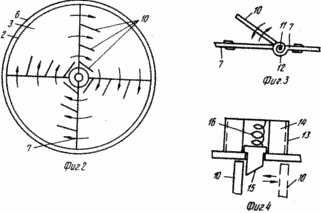 |
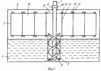
FIG. 1-4 shows the proposed device.
Flywheel variable moment of inertia (see. FIG. 1) comprises a shaft 1 on which is rigidly fixed hollow drum 2 with a camera 3 for a liquid 4 (see. Fig. 2). At the lower end of the shaft 1 is rigidly fixed tube 5. The entire structure is placed in the tank-housing 6 is not filled with liquid above the bottom of the drum lid 2, inside which there are radial partitions 7. The nozzle 5 is rigidly fixed screw 8 rigidly secured to the shaft 1. The upper drum cover 2 is provided with holes 9.
FIG. 3 shows the device return mechanism: 7 provided with radial partition flaps 10. The flaps 10 are placed rotatably on axles 11 which are provided with springs 12. One end of spring 12 is fixed axis 11 and the other end - for radial partition 7.
FIG. 4 lock mechanism is given: electromagnet 13 with a low voltage coil 14 is provided with a core 15 inside the moving coil 14 and a spring 16. The electromagnets 13 and spring 11 are located on the upper and lower covers 2 on the drum outer surface.
On the shaft 1 (see. FIG. 1) is rigidly fixed contact ring 17, insulated from the shaft 1. With the ring 17 contacts the elastic plate 18, through the sliding contact energized (low) to the coils 14 of the electromagnets 13. When necessary, braking in extreme conditions serves voltage via a sliding contact 18 on the ring 17, which disperses stress on the coils 14 of electromagnets 13 (see. FIG. 1) which are activated and retract the cores 15 (see. FIG. 4). Thereafter include braking. When premature braking unwound flywheel fluid, emphasizing the radial walls 7, which consists of flaps 10, is pressed onto the core 15 (see. FIG. 2, 4), and jammed their inclusion electromagnets will not be able to draw the cores inside the coils 14. The flaps 10 when the the electromagnets 13 are exempt from constipation-cores 15 and braking the shaft 1 under the pressure of the fluid opening, passing a rotating fluid. Due to poor adhesion of liquid to the drum walls 2 liquid stored energy is not transmitted to the shaft 1. During braking only overcome the inertia of the shaft with a screw in the pipe, the drum 2 with partitions, doors, combined mass is much smaller than the mass of the liquid. There is a kind of mass discharge from the flywheel shaft, allowing much to reduce the deceleration time. Liquid gradually slows the rotation drum 2 and stops. The springs 11 (see. FIG. 3) is returned to the original position of the sash 10, pivoting on axes 11, and radial partitions acquire a coherent structure.
Cores side flaps 15 have a bevel 10 (see. FIG. 4). This is to ensure that in case of failure when the voltage across the electromagnets nominated cores can be closed shutters: the flywheel is pushed in the opposite direction and folds, emphasizing the bevels cores, squeeze them and give birth to their seats, where the cores are fixed. Mechanisms of constipation must be placed above and below, as otherwise (one upper lock) when working fluid presses on the flap, inevitably will press, otognet unattached edge will break into the resulting opening and operation of the flywheel broken-decrease its effectiveness. When you stop the flywheel voltage is applied to the coils 14 of the electromagnets 13, 15 are drawn cores, flaps 10, rotating on axes 11 are closed (see. Figs. 3 and 4). Turn off the power, the electromagnets 13 and 15 cores released they fix sash 10: 7 radial walls are intact. The liquid from the drum 2 is discharged by gravity into the body and the reservoir 6 to 8. This screw design reduces the deceleration time of the flywheel. (56) Author's certificate USSR N 711312, cl. F 16 F 15/30, 1978.
CLAIM
FLYWHEEL VARIABLE MOMENT OF INERTIA containing connected to the shaft with the possibility to rotate together with the latter a drum with liquid chamber, inside which there are radial partitions, the liquid supply means into the chamber, characterized in that, to improve the safety of the flywheel operation, by reducing the braking time in extreme conditions, radial partitions mounted on spring-loaded flap rotatable on the axes and cooperating with controllable shut-off devices, which are fixed to the upper and lower end caps of the drum.
print version
Publication date 10.02.2007gg
![]()

Comments
Commenting, keep in mind that the content and the tone of your messages can hurt the feelings of real people, show respect and tolerance to his interlocutors, even if you do not share their opinion, your behavior in terms of freedom of speech and anonymity offered by the Internet, is changing not only virtual, but real world. All comments are hidden from the index, spam control.