| section Home
Production, Amateur Radio amateur Model aircraft, rocket- Useful, entertaining |
Stealth master
Electronics Physics Technologies invention |
space Mystery
Earth Mysteries Secrets of the Ocean Stealth section Map |
|
| Use of material is permitted for reference (for websites - hyperlinks) | |||
Navigation: => |
Home / Products Patents / In the section of the catalog / back / |
|
INVENTION
Russian Federation Patent RU2008512
![]()
Wind turbines with sailing-propeller engine
Name of the inventor: Aseev Valery Ishberdanovich
The name of the patentee: Aseev Valery Ishberdanovich
Address for correspondence:
Starting date of the patent: 1991.06.28
Use: wind power. The inventive wind turbine with a sail-propeller engine is equipped with a fixed on the sleeve 22, the horizontal shaft 1 main radial spokes 2, placed in two rows, between which are placed rims 3 is fastened on screw blades 6, consoles 15, connecting the hinge bushing 14 with turntable 11, which is placed on the wind turbine, and a stretching-emphasis 16 is connected to the upper part of the front shaft support 9 1. Rims 3 are connected to radial spokes oppositely disposed abutments 4 and 5. The horizontal shaft extensions 1 is mounted on two supports 9, 10. Turntable 13. The anchor 11 is provided with extra radial spokes disposed between the main radial spokes 2. Rear principal radial spokes 2 are fixed on the movable shaft along the axis of the hub 1 22 having restrictive screw slots 23 in which the guide pins are mounted on the shaft 1.
DESCRIPTION OF THE INVENTION
The invention relates to wind energy and can be widely used in all regions of the country.
Wind turbines designed to be installed both on a flat surface (land, water - on the platforms, rafts or ships, catamarans), and on elevated surfaces.
Known wind turbine drum with longitudinal helical blades disposed on the turntable [1].
Disadvantages of known design - low power density, the need for a plate vane, and low reliability and turntable.
The closest in technical essence to the claimed solution of a wind turbine comprising a shaft on which the one-way bearing is fixed coaxially with the wind wheel with blades arranged in tiers between them [2].
Disadvantages of known design - stationary, a large load on the swivel head and the tower-support when trying to increase the wheel size - with an increase in the sail increases exponentially load bearing and overturning moment. The presence of unilateral support limits the size of both the propeller diameter, and on top of it.
This design requires additional devices focusing on the wind (weather vanes and so on. N.). In addition, the consumption of materials design, dimensional, complex and and low-tech, but also immobile and difficult to use.
The purpose of the invention - increasing power, strength, mobility, simplification of the design, manufacturability and operation.
This object is achieved by the wind turbine with a sail-screw motor comprising a horizontal shaft with bearings and coaxial arrangement of the rim on which the fixed helical blades, generator, kinematically connected to the shaft, and a current collector, is provided with a main radial spokes, which are fixed rims, and between opposing spokes fixed angle supports and stretching, and the shaft is mounted between two resilient to lateral load supports fixed to the turntable, held via the armature fixed relative to the platform center of rotation and connected via a rotatable sleeve on which are fixed console platform, and via the stop-stretching the upper part of the front supports and the blades along their length oriented at an angle to the shaft axis.
Furthermore, with increasing wheel diameter between the major radial spokes secured additional radial spokes.
To improve the reliability of the at higher wind loads and increasing the number of tiers of blades, the rear main radial spokes secured to movable along the axis of the shaft and rotatable about this axis sleeve having restrictive screw slots that contain, guide pins fixed to the shaft, wherein stretching stops and installed at an angle to the shaft axis, equal to the angle of the blades installation.
 |
 |
 |
 |
 |
 |
 |
 |
 |
 |
 | |
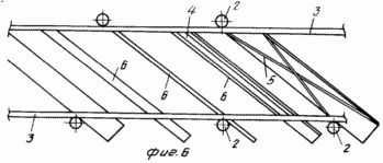
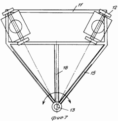
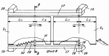
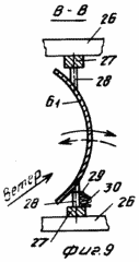
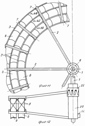
FIG. 1 is a diagram of wind turbine, side view; FIG. 2 - view along arrow A in Fig. 1; FIG. 3 - Profiles of blades; FIG. 4 - assembly reducing wind load, longitudinal section; FIG. 5 - view along arrow B in FIG. 4 (performing helical grooves on the movable rotary hub); FIG. 6 - The location and orientation of the blades and stops, stretching and changing the angle of attack of the blades and the angle of the stops-stretch with wind load above the permissible; FIG. 7 - top view of the platform and castors; FIG. 8 - a front view of the blade; FIG. 9 - section B-B in FIG. 8; FIG. 10 - top view of the thrust and rotation synchronous control spring; FIG. 11 - front view of the wind wheel; FIG. 12 - the same as the top view.
Wind turbine 1 comprises a shaft with radial main spokes 2, which are mounted on the coaxial rims 3 (in this embodiment, the rim used three) connected to the inclined shaft 1 stops 4 and 5, stretch marks.
3 on rims and spokes 2 fixed blade 6, which length oriented at an angle to the axis of the shaft 1. The stops 4 and 5, stretch oriented at the same angle as the blade 6.
Blade 6 are primarily rectangular in shape with various and subsequent profiling cross-section (FIG. 3) and the rims are smaller in length spin by a certain angle.
By increasing the number of tiers and the number of rims 3 mounted intermediate between the major spokes 7 with needles 2, which in this case is increased in length to increase the strength of the spatial propeller.
The shaft 1 is located on the bearing supports 8 and is mounted on two lateral load-resistant supports 9 and 10, respectively front and rear, for example, a triangular shape mounted on a turntable 11 which can have different supports, such as wheels 12.
Platform 11 is retained anchor 13 configured to facilitate its penetration and hardening fixation in soil lockable in the center of the platform 11, the axis of rotation and connected via a hinge sleeve 14 with cantilever arms 15 with the platform and at least one stretch-stop 16 with the upper part of the front support 9 shaft 1. on the shaft 1 is mounted a pulley 17, kinematically connected for example a belt transmission 18, to a pulley 19 of the generator 20, generating electrical current, which via the current collector (brush assembly) 21 mounted on the anchor 13, is passed to the consumer.
To avoid overloading the wind needles 2 from the rear support 10 mounted on a movable along a shaft 1 and rotatable around its axis of sleeve 22 having helical grooves 23 restrictive, in which are arranged pins 24 fixed to the shaft 1.
The sleeve 22 is mounted on tension springs 25 fixed to the shaft 1 or 2. Between the spokes 22 and the end face of the sleeve 8 supported by the rear support 10 is performed, the gap at the working gap X helical scanning length 23 of the slot.
Each of the blades 6 depending on the length divided into several parts, in this embodiment - two parts (louver) 6 1 and 6 February.
26 are mounted on frame crossbeams 27, which on axes 28, each rigidly mounted blade part 6 in such a way that part - is divided into two unequal lengthwise section, a length L 1 and length L 2 other.
On the axes 28 and 29 are fixed pivot levers, one of which is connected to the control spring 30 to wind load. The levers 29 are interconnected by rod 31 synchronous rotation.
Wind turbine works as follows
The pre-selected location for its installation, preferably flat or elevated place and enough solid foundation - the circle to move the truck - platform 11. Fix the anchor 13 and produce all the necessary electrical connections.
Under the influence of the wind wheel starts to rotate at the same time focus on the wind. This contributes to sustainable shifted the center of gravity position of the wheel relative to the axis of the fulcrum of the armature 13. When the coincidence of the wind direction with the axis of the shaft 1 there is the greatest performance of the wind turbine.
By increasing the speed of the wind increases the load on the wind wheel, but it does not affect the strength of the installation, as the system console, 15 and 16 run stretching tension, and supports 9 and 10 have to load almost by weight propeller. This fact can significantly facilitate the design without using heavy and bulky tower - foundations that are traditionally used in the prior art.
If the wind load still exceeds the limit that affects the allowable strength of the wheels, under the influence of the wind moving the rear part of the propeller starts relative to the stationary front at the same time to turn and move, respectively, around and along the axis of the shaft 1, overcoming the resistance of the spring 25, due to the directional movement sleeve 22, on which the entire rear part of the wheel is mounted, with the slots 23 and pins 24.
At the rear of the blades begin pazvopot 6 stops 4 and 5 extensions, and as a result, decreases the angle of attack of the blades 6, predominantly large-diameter, into tiers which accounts for the largest load.
When the wind with a speed exceeding the permissible, as a result of the impact of wind flow on the part of the June 1 and June 2 blades is their synchronous rotation and skipping past the flow of parts June 1 and June 2.
At large distances coaxial tiers n = 36, 42, 48.. . bladed propeller 6 from the center of rotation is achieved by a large sail, and thus power.
When long distance coaxial tiers suitable installation of the generator 20 on the axis of the propeller 1 with optional brush assembly 32.
By reducing the angle of attack of the blades of wind 6 number of them in tiers, you can increase or install the blades 6 lengths. The windmill can produce a large width and spatial strength.
Wind turbine requires scarce materials in large quantities, and a complicated equipment for its manufacture and installation. Reliability and durability make this a promising wind turbine for use in eco-friendly and cost-free in terms of fuel resources, energy.
(56) 1. US patent N 4086026, cl. F 03 D 1/06, publish. 1978.
2. Application of Germany N 2909781, cl. F 03 D 1/06, publish. 1980.
CLAIM
1. Windmill with sailing-propeller engine having mounted on a turntable horizontal shaft with the hub and a coaxially positioned rims, which are fixed helical blades, generator, kinematically connected to the shaft, and a current collector, characterized in that, in order to increase reliability and power increase, it is provided with fixed to the hub in two rows major radial spokes between which rims connected to the oppositely disposed needles abutments-braces, a shaft mounted between two supports placed on a turntable, held by means of anchors fixed about the center of rotation of the platform and connected via a hinge assembly consoles connecting hinge assembly with the platform, and a streamer-emphasis connected to the upper part of the front support, wherein the blades are oriented along the length thereof at an angle to the shaft axis.
2. The wind turbine of claim. 1, characterized in that between the basic radial spokes mounted additional radial spokes.
3. The wind turbine of claim. 1, characterized in that the rear radial main spokes mounted on a movable along a shaft axis and rotatable around the axis of the sleeve having a helical slot restrictive, in which guide pins mounted fixed on the shaft, wherein the stops are set and streamers at an angle to the shaft axis, equal to the angle of the blades installation.
print version
Publication date 10.02.2007gg


Comments
Commenting, keep in mind that the content and the tone of your messages can hurt the feelings of real people, show respect and tolerance to his interlocutors, even if you do not share their opinion, your behavior in terms of freedom of speech and anonymity offered by the Internet, is changing not only virtual, but real world. All comments are hidden from the index, spam control.