| Start of section
Production, amateur Radio amateurs Aircraft model, rocket-model Useful, entertaining |
Stealth Master
Electronics Physics Technologies Inventions |
Secrets of the cosmos
Secrets of the Earth Secrets of the Ocean Tricks Map of section |
|
| Use of the site materials is allowed subject to the link (for websites - hyperlinks) | |||
Navigation: => |
Home / Patent catalog / Catalog section / Back / |
|
INVENTION
Patent of the Russian Federation RU2013652
![]()
ENERGY INSTALLATION
The name of the inventor: Markelov Vasily Foteevich
The name of the patent owner: Markelov Vasily Foteevich
Address for correspondence:
The effective date of the patent: 1991.03.29
Use: to generate energy. SUMMARY OF THE INVENTION: The power plant comprises a vertical windmill with blades mounted on a cylindrical float located in a reservoir with a fluid and kinematically connected to a working machine placed on the base. The rotor is made in the form of connected triangular skeletons whose vertices are offset in the circumferential direction relative to each other. The blades are pairwise mounted on the edge of each frame by means of hinges with an elastic coupling, and the area of each pair of blades is equal to the side of the frame. The float is provided with a rolling element placed on its vertical generators and a counterweight. The inner surface of the tank is spherical, the rolling elements being in contact with the latter.
DESCRIPTION OF THE INVENTION
The invention relates to power engineering and can be used to provide consumers with energy stored in water and air.
Already known is a wind power plant containing a wind turbine and driving an air compressor whose compressed air feeds the air motor. The scheme uses a pneumatic accumulator and an electric generator (British application No. 2112463, cl. F 03 D 9/02, 1983). However, this installation uses a piston air motor and therefore does not use the selection of heat from the liquid when the expanding volume of gas inside the float-bell rises, which reduces the efficiency.
A solar plant is known that uses the greenhouse effect and represents a solar collector for heating water in a solar collector used for heat supply. The efficiency of such an installation is close to 100%. But the heat accumulated in water, with the existing methods of transformation, is not used to generate energy.
Finally, a plant containing a pneumatic hydrogen engine connected to a source of compressed air is known. Although the prototype uses a float-type air-hydrogen engine containing a floating cylindrical body with a bell-shaped float fixed in it by means of flexible connections, capable of making vertical displacements inside the housing for the length of the links and at the same time performing work, but the limited travel of the float by flexible bonds and the lack of a calculated formula for the effective volume of the compressed Air, initially supplied under the float does not allow you to determine the parameters of the installation and lead to a decrease in efficiency
In the proposed installation, it is essential that, in addition to the traditional conversion of various manifestations of energy, the most effective extraction of solar energy accumulated in water and air is provided. The energy-extracting properties are due to the following facts.
The properties of chemical elements and compounds (a mixture of gases that make up air and a combination of hydrogen and oxygen that make up water) are used, which determine both the initial and acquired unevenness, a necessary condition for creating a permanent machine.
Archimedes' law is considered as a consequence of the law of conservation of energy, when the buoyant force at equal temperatures of a fluid and a body is viewed as a consequence of the difference in energy costs produced or the phase transition from one state to another with a change in body density with a constant fluid density and which determines the degree of buoyancy - , When the buoyancy force is greater than the pulling force, zero when the ejection force and the retraction force are equal and negative when the ejection force is less than the retraction force. The formula of Archimedes' law is proposed in the following edition: "A body immersed in a liquid is acted upon by a force determined by the difference in the expenditure of energy to create a fluid and a body or to a transition to another aggregate state, accompanied by a change in the densities (if the liquid is not water) , Accumulated fluid and body within the temperature of formation or transition to another aggregate state (meltdown, solidification, gas formation. "
The buoyant force acting on the water or other liquid introduced into the column is the initial volume of gas or air with positive buoyancy, greater than the force necessary to overcome the pressure of the liquid above the pressure port of the compressed gas source by the amount of force providing positive buoyancy.
The buoyant force acting on the volume of gas that has a positive buoyancy, put under the column of water at equal temperatures of water and gas, increases as the surface ascends and pressure decreases over it with an increase in the volume of the gas by the amount of the initial volume every 10 m of ascent (1 at).
The buoyancy force increases practically at a constant water density within the temperature range from 0 to 100 о С, whereas the gas increases its volume by 1/273 of the initial volume per degree of temperature increase, i.e., changes the density depending on the amount of energy expended more intensively than water , Disturbing the equilibrium of the energy potentials of water and air, and is observed when there is a temperature difference between the liquid and the gas.
The buoyant force increases, since the air intake practically occurs in an isolated water system with a low thermal conductivity (adiabatic process), when a pressure drop of 1 atm causes a decrease in the air temperature by about 24 ° C, ie, air is almost always supplied Under water with a temperature below the water temperature, which makes it possible to efficiently extract energy at equal temperatures of water and air and close to 0 ° C.
A useful work is done by the average effective volume of air, which, when interacting with water, is determined from the relation ![]()
The coefficient (1 + 0.5 P) reflects the initial nonequilibrium, and ( ![]() ) - acquired, where V d - the actual volume of gas, V n - the volume of compressed gas at absolute pressure, P - pressure coefficient, depending on the height of the water column, t - water temperature, t 1 - air temperature.
) - acquired, where V d - the actual volume of gas, V n - the volume of compressed gas at absolute pressure, P - pressure coefficient, depending on the height of the water column, t - water temperature, t 1 - air temperature.
All the above is supported by the following conclusions and experiments.
Let us pay attention to the arrangement of chemical elements in the periodic system. It can not be overlooked that all of them are located as their atomic weights increase, that is, because of nonequilibrium. It can not be denied that a different amount of energy was expended on their creation by nature, and this difference determined the properties of elements, such as density, heat capacity and thermal conductivity. In this series there is hydrogen, iron and mercury. In mercury, both hydrogen and iron will float, but the amount of work produced will be greater for hydrogen than for iron. But they do not stand side by side in the system and have different density, heat capacity and thermal conductivity. This is an example of when the work is done at the expense of the initial disequilibrium.
But when the volume of air brought up under the column of water increases not only due to an increase in pressure over it during ascent, but also due to a positive temperature difference between water and air, then in this case the work is done at the expense of both the initial disequilibrium and the acquired one.
It is known that at the location of 1 g of ice, taken at 0 ° C, it is necessary to spend 80 cal. The melting of 1 ton of ice taken at 0 ° C requires 93 kWh, while water will have a temperature close to 0 ° C (phase transition point from solid to liquid state and vice versa). This means that in 1 ton of water at a temperature close to 0 ° C, not less than 93 kW / h of energy is accumulated.
What is water? This is one of the states of water as a substance (liquid), but water is also a melt of ice, and the ice in it floats. But in their melt, both lead and iron float, the solid state of matter floats in its melt. In both cases, energy was used to prepare the melt, creating a difference in the energies of the liquid and solid state of the substance. If we use artificially obtained energy to prepare lead melt, we prepared nature's melt of ice (water) and ice itself, which maintains the necessary energy regime, in which the water is in a liquid state and the amount of energy is accumulated in 1 m 3 of water at a temperature close to To 0 ° C is comparable with the amount of energy released when burning 1 m 3 of firewood.
To the neck of the bottle we tie the load so that the bottle in the water floats and occupies an upright position. Let's release some of the air replacing it with water and get to this position when the bottle just begins to sink and plug the bottle under the water with a cork, turning it into a sealed float. After changing the water to a hot one, let us drop the bottle into the water. The temperature of cold water is 20 о С, hot - +45 о С. The bottle is the same as in the first case, when the water is cold, it will sink. At the same time, the air volume, mass, density remained unchanged, but the internal energy of the air changed. We take out a cork under the water, turning the bottle into a float-bell, the bottle will float up and protrude above the water about 10 mm. Before dropping the bottle into the water with a rubber ring, note the water level in the bottle. Under hot water, plug the cork and take the bottle out of the water. The expanded volume of air displaced water from the bottle. Knowing the initial volume of air in the bottle, the resulting volume and temperature of cold and hot water, in the calculation, we find that an increase in the primary air volume accounted for 1/273 for each degree of air temperature increase, and this is the Gay-Lussac law formula, which looks like this: ![]() , Where t is the difference between the temperatures of water and air;
, Where t is the difference between the temperatures of water and air;
V o is the primary volume of air.
When we adjusted the bottle at the beginning of the moment of immersion, creating the conditions for occupying the bottle with an indifferent position, we thus leveled two forces - the force of attraction and the force of the tug, ie, brought these conditions closer to the conditions of weightlessness. Adjusted in this way, a bottle or a container with an open lower part will be lowered in the morning to the cold water of a natural reservoir (water overnight has cooled down, and temperature drops, for example, in the steppes of Kazakhstan reach 25-30 ° C, which we can increase by connecting a solar collector, Heating water in the daytime and cooling in the night). A bottle or container will sink. As the pond warms up with the sun, and the solar radiation power averages 1 kW / m 2 , the air in the bottle or container simultaneously with the water of the reservoir will begin to warm up and because of the difference in the specific heats of water and air and the coefficient of volumetric expansion associated with it will increase in volume More than water, pushing it out of the bottle. A bottle or container will pop up and depending on the size of the bottle or container, the temperature drop will work. In the evening, the water will begin to cool down, and by the morning the bottle or container will not just sink, but will be drawn into the water. At the same time, if the temperature difference is equal, an equal amount of energy will be produced as in the case of ejection. With the beginning of the warming of the reservoir, the sun will begin to ascend, and the cycle will repeat. We will get a rather efficient permanent solar installation of the type operating a perpetual second-generation engine in which the energy difference of the two initially nonequilibrium media contributes to the extraction of solar energy that created the acquired disequilibrium of the interacting substances and media.
When we adjusted the bottle in cold water to the beginning of the dive moment, replacing part of the air with water, we thus removed some of the buoyant force that provided the ascent (positive buoyancy), and simultaneously equalized the amount of matter displaced by the bottle of water and the bottle itself with the cargo attached to it and its (Water, air), that is, the weight of the bottle with water, cargo and air in it is equal to the weight of the displaced water, i.e., the buoyancy force is zero (zero buoyancy), the difference in the external water and system potentials, the load, the glass of the bottle , Air and water in the bottle is also zero. But to achieve this, we removed not part of the force of attraction, but part of the pushing force, which means that if the force of attraction in this case existed, then for a body with positive buoyancy it would still be less than the pushing force, That is, it is not present in this case, and it can not occur until the bottle adjusted for zero buoyancy is in the water, and the difference in the energy potentials will be zero, since the buoyancy force acting on the unchanged volume of the body does not depend on the depth of immersion , Especially when instead of a solid body gas is applied with its positive buoyancy, the ability to increase in volume as it surfaced and temperature changes.
On the body under the conditions of zero buoyancy there are two oppositely directed and equal forces - the pushing force directed upwards and the pulling force directed downwards. The force of ejection increases with the increase in the positive difference in the energy potentials of water and air with the total absence of the force of attraction, and the retraction force with its negative difference. Let us trace the conclusions drawn on the formulas.
On the Earth's surface, the attractive force is F = mq, where m is the mass of the body, q is the free fall acceleration of 9.81 m / s 2 .
On the surface of the Earth, the pulling force is F = V 'D'q, where V is the volume of the body, D is the density of the liquid (in this case water), q is the free fall acceleration of 9.81 m / s 2 . But VD is m. Thus, on any volume of liquid in the column of this fluid at any depth, an ejecting force equal to the force of attraction acts, and this is the same indifferent position of the body in the liquid, as in the case of the bottle, and this is the case if we pumped Water, and when returning the displaced water through a turbine with a efficiency of 1, we obtained an amount of energy equal to what was spent, but we do not inject water under the water, but rather have air that has positive buoyancy.
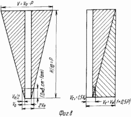
Let us examine in more detail the effect that follows from Archimedes' law. The floating body is submerged by some of its part in the liquid: the submerged part displaces by weight as much liquid as the whole body weighs. We can say that a buoyancy force acts on the floating body, equal to the weight of the fluid displaced by the submerged part, and we will make a mistake. After all, the air above the surface of the water, also possessing a positive buoyancy, can be taken as a floating body. However, with a constant amount of air dissolved in water (drawn in), there is no immersion of air into the water, but it is pushed out of it without remnant, i.e. with greater force, although the air column above this body can exceed the body weight. But if you immerse a floating body and a pillar of air over this body to some depth, then the energy of the air column is much more closed than the immersion of the body. In both cases it would be necessary to overcome the buoyancy force (positive), that is, when the buoyancy force is greater than zero. And we were convinced that the buoyancy force at the stage of ascent at equal temperatures of water and air is greater than the force of attraction. Nonequilibrium is a necessary condition for creating a periodically operating machine, which does not contradict the second law of thermodynamics and the law of conservation of energy. But if a solid body can not be brought under the pillar of a liquid without having overcome the force (we are forced to sink the body from the surface of the reservoir), then the air can be reduced, bypassing the energy spent on overcoming buoyancy. This is yet another proof of why less energy is required to supply the volume of air under the water column than to overcome the pressure of water above the pressure nozzle of the source of compressed air, as is clearly seen in Fig. 8. Since the primary volume of air supplied also has a positive buoyancy, it is clear that upon ascent, we obtain a gain in energy due to the heat collected from the water and the difference in the cost of energy to create a fluid and a body.
We take the funnel, turn it upside down and lower it into the water so that the lower expanded part does not reach the bottom, and the upper one was at the water level or slightly higher. We bring air to the funnel by the tube. Let us make sure that the water displaced from the funnel is not just poured from the nipple but gushes to a considerable height, that is, an almost non-increasing volume of air due to the buoyancy force creates a pushing force that is not observed when the same volume of water is supplied, Efficiency = 1, we could get the amount of energy equal to the spent energy. But for air supply we spend less energy than on water supply, nevertheless we get a gain in energy. This is not the principle on which the action of the injector or ejector is based, but the phenomenon caused by the difference in the cost of energy to create water and air (the initial disequilibrium) that determines their properties. It is known that the volume of air with a pressure drop by 1a increases by the amount of the initial volume, i.e., the initial increase in the volume of air occurs or, more accurately, is equal to an increase by a factor of 2, but the average operating volume of air works on energy production (Figure 8), Which is expressed by equation ![]() , Where V o is the volume of primary air at a depth H at the same temperatures of water and air;
, Where V o is the volume of primary air at a depth H at the same temperatures of water and air;
H is the height of the water column,
P - coefficient of pressure, depending on the height of the water column (Nm / 10 m = P) at the level of the bottom float-bell or annular distributor of compressed air.
Then ![]()
The obtained equation allows us to calculate the energy production due to the initial nonequilibrium at equal water and air temperatures, and the Gay-Lussac law is the calculation of the additional energy received due to the acquired disequilibrium, when the water and air temperatures are not equal. The above conclusions relate to pneumohydrodynamics, but for their launch an additional source of energy, a sort of starter, is needed. Such an energy source could be one of the environmentally friendly converters of non-traditional energy sources. In this case, a wind power plant with an increased wind load removal area representing a vertical rotor is selected as such a converter.
It is known that in an equilateral triangle the point of intersection of the bisector is at 1/3 of the height of the triangle and if we make a skeleton representing a prism whose bases are an equilateral triangle, and some of the sides of the prism are shrouded by an impermeable material and through the intersection of bisectors pass the axis, Rotor element of a wind power station. Having installed several such elements on top of each other with mixing in a radial direction around the axis, we obtain a rotor, we obtain a rotor, and by installing additional spring-loaded sail blades equal in area to the main generators, which are capable of opening under the action of wind, we obtain an additional area for removing the wind load . Having installed such a rotor on the float, we get a wind power plant, capable of operating at storm speeds of the wind. We connect the upper platform of the float with the wheel fixed to the rack, which has the possibility of vertical and circumferential movement, with the compressor installed on it and connected by an intermediate transfer with the wheel, which is connected to the power-extracting air-hydraulic engine by the pipeline; the energy in the water is replenished by the solar collector connected to it , Which uses the greenhouse effect. The energy-extracting air-hydrogen engine is connected to a compressor that is connected to the compressor by a pipeline with an energy-recovery water-jet installation representing a cylindrical fixed fixed body on the bottom of the reservoir, closed at the top and open in the lower part, which is at the top of the nozzle, and in the upper part of the nozzle Bottom on the inside - fixed at an angle plates acting as turbine blades, and located in a river or canal closed with a reservoir, which extracts energy accumulated in the reservoir.
Thus, the main distinguishing features of power plants are energy-extracting properties as opposed to converters of one manifestation of energy into another.
 |
 |
||
| |||
 |
 |
||
| |||
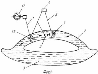
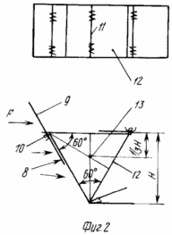
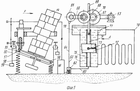
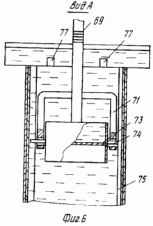
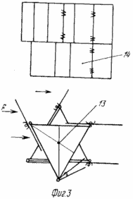
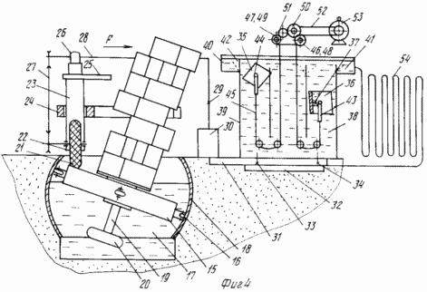
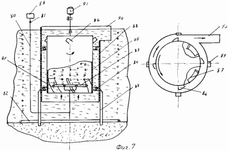
In Fig. 1 shows the scheme of the power plant; In Fig. 2 - rotor element of the wind power plant; In Fig. 3 - multi-stage rotor of the wind power plant; In Fig. 4 - wind power plant; In Fig. 5 - the same, with a spring-loaded platform and counterweights; In Fig. 6 is a view A of Fig. 5; In Fig. 7 - power-extracting water-jet installation; In Fig. 8 - diagram of the operation of the volume of air supplied under the column of water at equal temperatures (the right part represents the graph of the average operating volume of air).
The power-extracting wind power plant 1.1 is connected by an air duct 1 to an energy recovery unit of the water-jet type 1.2 installed in the channel 2 closed with a water reservoir 3 connected to an energy consumer, for example, a compressor station 4 and a fan 5. The compressor is connected by an air duct 6 to a refrigeration unit 7 located above the channel And designed to condense water vapor of atmospheric air. The sail blades 8 and 9 (Fig.2) between which there is an elastic element 10 hingedly connected to the vertical generators 11 of the spatial prismatic frames 12 representing the triangular prism and connected by the bases to each other with displacement relative to each other around the geometric axis 13 of the prism and constituting the vertical rotor 14 (Figure 3) fixed to a cylindrical float 15 (Figure 4) having rolling elements 16 on a vertical generatrix and placed in a reservoir 17 filled with a liquid and having an internal spherical surface 18. At the bottom of the float, the rod 19 is secured with a load 20 at the end . The upper surface of the float interacts with the wheel 21 fixed in the supports 22 on a vertical post 23 that is vertically displaceable in the annular guide 24 with simultaneous movement in the circumferential direction. On the top of the rack there is a platform 25 with a compressor 26, which interacts with the wheel via an intermediate gear 27. The compressor by the duct 28 through the check valve 29 is connected to a compressed air accumulator 30 which, by the air duct 31 through the on-off distributor 32 and the valves 33 and 34, alternately connects to the bell-shaped bellows 35 and 36, each of which is divided by a hollow horizontal partition filled with air into two equal in volume Parts. The float-bell is asymmetric with respect to the vertical axis. The float-bell interacts with the guide parts 38 and 39 of the body of the air-hydraulic motor filled with water and passing into the expanded discharge part 40 in the upper part of the body. The float-bell interacts with those fixed in the upper part of the body at the border of the transition of the guiding part to the unloading with the elastic return members 41 and 42 and hinged on the floats at the point of the center of gravity with the frames 43 and 44 that are interconnected by a common cable with the trolley gear 45. The cable of the crossover transmission interacts with the drums 46 and 47 freely set on two parallel axes and interacting with the drums through the overrunning clutches 48 and 48. The drums interact through the gear 50 and the parasitic gear 51 and through the intermediate gear 52 with the compressor 53. The water filled The body of the air motor is connected to the solar collector 54. Depending on the operating conditions, the rotor 14 can be mounted on the rotating platform 56 of the platform 56 (FIG.5) interacting with the base 57. The base rests on the springs 58 and has counterweights 59 which, The compressed air accumulator 61 through the inlet valve 62 and the rod 63 with the primary start pedal 64 through the cam mechanism 65 connected through the intermediate gear 66 through the overrunning clutch 67, the gear 68 with the rack 69 and the inertia flywheel 70. The rack is integral with the frame 71, pivotally connected to the bell float 72, divided by a partition 73 into two equal parts in volume. The float-bell cooperates through the journals 74 (Fig.6) with box guides 75, with the walls of the water-filled body 76 and elastic return members 77 mounted on the boundary of the transition of the guide part to the discharge part 78. The fluid-filled body of the air-hydraulic motor is connected to the solar collector 79, The bell float 80 with an intake valve and the inertial flywheel with a compressor 53. The compressor 53, through the air duct 80 (Figure 7) with the check valve 81, interacts with the annular tube air sprayer 82 and the multi-ring air distributor 83 located inside and above The lower part of the cylindrical body 85, closed in the upper part and the lower water level, which is closed in the upper part and located at the lower water level and which has in the upper closed part a vertical generatrix on the outside of the nozzle 86, the total cross-sectional area of which is not less than the cross-sectional area of the body. In the lower part of the housing 85, plates 87 are fixed to the generatrix from the inner side at an angle. The housing 85 interacts through rolling elements with a fixed outer cylindrical body 88 fixed with piers 89 in the bottom of the channel and having a water outlet at the level of the nozzles of the inner shell , Interacting with the electric power generator 91. The upper part of the housing 85 is higher and the lower part is lower than the upper and lower part of the inner case. Consumers of electrical energy can be, for example, a compressor 4 and a fan station 5 operating in a quench with a refrigeration unit 7.
ENERGY INSTALLATION WORKS AS FOLLOWING
The energy recovery windmill 1.1 (Figure 1), which produces compressed air by pipeline 1, is connected to an energy recovery unit of the water-jet type 1.2 installed in channel 2, closed with a reservoir 3. The possibility of obtaining an unlimited amount of energy allows us to connect the compressor 4 and the fan station 5 , Working in conjunction with the refrigeration unit 7 in order to obtain fresh water due to condensation of atmospheric air vapors. The energy necessary to ensure the operation of the compressor and fan or other consumers is obtained by converting wind energy into compressed air energy with the further increase in the amount of compressed air due to the energy extracted in the energy recovery pneumatic engines connected to the wind power plant and solar collector through the use of compressed air In an energy recovery unit of the water-jet type, in which the energy accumulated in the water of the reservoir is extracted. The electric power received by the proposed method is environmentally friendly.
The wind power plant works as follows. The sail blades 8 and 9, between which the resilient member 10 is located, are pivotally connected to the vertical generators 11 of the spatial frames 12 representing the triangular prism and connected by bases with displacements relative to each other around the imaginary geometrical axis 13 and constituting a vertical bubble rotor 14 fixed On a cylindrical float 15 that has rolling elements 16 on a circumferential vertical wall and is placed in a reservoir 17 filled with a liquid having an inner spherical surface 18 and the float has a rod 19 at the end of which a load 20 is fixed while a float acting as an inertial flywheel , Represent the construction of an unprimmed vertical rotor in which air sails and an elastic element are opened by sailing blades, driving a prefabricated vertical rotor and a float connected to it, which, when the wind increases, can bend without leaving the spherical surface of the tank and with a weakening of the wind Due to the reduced center of gravity provided by the load, again assumes a vertical position. Thus, self-regulation of the load on the rotor takes place, which ensures the operation of the installation at storm speeds of the wind. The upper surface of the float contacts the wheel 21 fixed in the rolling supports 22 on the post 23, which is capable of under its own weight of vertical and circumferential movement of the guide 24. On the upper part of the post there is a platform 25 with a compressor 26 which interacts with the wheel shaft via an intermediate gear 27. Thus, the rotation of the float is transferred to the wheel which, via an intermediate gear, transmits it to the compressor drive, which is connected via a non-return valve 29 to a compressed air accumulator 30 from which air through conduit 31 through the on-off distributor 32 and valves 33 and 34 is alternately supplied Under the floats of the bell 35 and 36, having a supply of useful volume, each of which by a partition 37, the cavity of which is filled with air, is divided into two equal parts in volume. Air in the cavity of the partition balances the weight of the float and the elements of the unit connected to it. The lower part of the submerged float is filled with air so that by the time of ascent the entire volume of this part is filled with air and when exiting the guide part it allows it to turn over 180 ° and be released from the volley with air, and again fill with water in the underwater position in the expanded unloading part 40. When In this case, having a useful volume of the float-bell as the ascending and lowering of the fluid pressure and the difference in the temperatures of the water and the supplied air increase, it increases the ascent force by increasing the volume of air accompanied by the selection of heat from less heat-intensive air from more heat-intensive water (Fig. Floating and flipped float-bell with elastic return elements 41 and 42 is fixed in the vertical working position. The bell floats are interconnected through hinges 43 and 44 that are hingedly connected to the floats, which are interconnected by a common cable with a trolley conveyor 45. The trolley transfer interacts with the drums 46 and 48 freely rotating on two parallel shafts and interacting with the drums via the overrunning clutches 47 and 49. The drums interact with each other through the gear 50 and the parasitic gear 51, which provides one-sided rotation of the gear wheel. The rotation of the gear is transmitted via the intermediate gear 52 to the compressor 53. To replenish the energy in the water of the airgun, the latter is connected to a solar collector 54 in which the water can be heated to a temperature close to 100 ° C. When the rotor 14 (FIG. 5) is mounted on a spring- The role of the fluid is carried out by compression springs 58, the load on which is reduced by counterweights 59. The advantage of this design is that the wheel transmitting rotation on the compressor is in contact with the dry surface of the platform, which will increase the frictional force, and when using the apparatus in the presence of water shortage, for example in Desert. Due to the fact that a single-float air-hydraulic engine is used, the air intake under the float-bell is effected by an automatic cam-shaped distributor, the rod of which is connected to the inlet valve. To replenish the energy reserves, the air-hydrogen engine is connected to the solar collector. The compressor 53 of the wind power plants through the air duct 80, when the valve 81 opens, supplies air to an annular pipe fryer 82 and a multi-ring tube air distributor 83 (Figure 7) located inside and above the lower open part, supported by rolling elements 84 closed at the top and located Below the water level of the cylindrical body 85 having in the upper closed part a vertical generatrix on the outside of the nozzle 86. The total cross-sectional area is not less than the cross-sectional area of the body and at the bottom is fixed at an angle of the plate 82 on the inner side of the housing 85. The housing 85 cooperates Through rolling elements with an open outer and cylindrical body 88 fixed in the upper and lower portions fixed by piles 89 in the bottom of the reservoir and having a water outlet 90 at the level of the nozzles of the inner case interacting with the electric power generator 91. When air enters the annular fish barrier, From it through the holes, forming an air curtain repelling the fish, preventing the fish from entering the unit. The air entering the multi-ring distributor inside the inner shell, coming out of the hole, being buoyant, increases its volume by the amount of the initial volume every 10 m of ascent and by 1/273 for each degree of temperature rise, begins to float, increasing its volume until the moment Out of the water, displacing the water through the nozzles. In this case, the heat from the water is taken from the calculation that when the air pressure decreases by 1 atm, the air temperature decreases by 24 ° C. There will be no outlet of water and air from under the cylindrical housing, since the air outflow from the multi- And the total cross-sectional area of the nozzles is not less than the area of the transverse casing, i.e. the water pressure to the bottom of the casing is greater than the water pressure to the distributor, and the equal or larger cross-sectional area of the nozzles and casing provides equivalent water inlet and outlet from the casing. The water ejected from the nozzles rotates the housing and the generator connected to it. Rotation of the body will have a constant speed. Discharged into the gap between the outer and inner bodies, water is discharged into the reservoir through the directional outlet available in the outer casing, creating a directed surface flow of aerated water. At the same time, a bottom current is created, directed inside the rotating inner body, and acting on the inclined plates, the water flow creates an additional torque. In this case, there is a constant replacement of the energy carrier, which makes it possible to obtain a uniform flow of electricity. The calculation of the additional power due to the bottom current can be made using the formulas for hydraulic turbines. Divided in a multi-ring distributor into small volumes, air has a large contact area with water, which contributes to the most complete selection of heat from water, which means that according to the Gay-Lussac law and the largest increase in air volume, which increases the amount of work done, Extracted energy.
Technical and economic efficiency will be expressed in using practically ready energy for the needs of the national economy, cheapness, inexhaustibility and absolute cleanliness of which allows not only to restore the lost equilibrium on the planet, but also to improve it.
CLAIM
1. ENERGY INSTALLATION comprising a vertical wind turbine with blades mounted on a cylindrical float located in a reservoir with a liquid and kinematically connected to a working machine placed on the base, characterized in that, in order to improve the efficiency of using wind energy, the rotor is made in the form of coupled Triangular skeletons whose vertices are offset in the circumferential direction relative to each other, the blades are pairwise mounted on the edge of each frame by means of hinges with an elastic coupling, and the area of each pair of blades is equal to the side of the carcass side, the float is equipped with rolling elements placed on its vertical generators and a counterweight , The inner surface of the tank is spherical, the rolling elements being in contact with the latter.
2. The power plant according to claim 1, characterized in that it is provided with a stand with a wheel mounted vertically with an annular guide, the working machine is in the form of a compressor fixed to the site and kinematically connected to a wheel mounted to interact with the surface of the float .
3. Power installation according to. 1 and 2, characterized in that it is provided with a liquid filled tank with guides and an upper unloading part, elastic return members, two bundled bobbins connected to the bobbins mounted in the tanks on the guides, a solar collector connected to the tank, two parallel drums interacting With a trolley transfer, an intermediate transfer connected to the compressor, a pipeline with a check valve connected to the compressor, and a compressed air accumulator, connected by a pipeline with two-position distributors with bell-floats.
4. Power plant according to. 1 - 3, characterized in that each float-bell is equipped with a horizontal partition installed with the formation of two chambers of equal volume, and is positioned asymmetrically with respect to the vertical axis.
5. The power plant according to claim 4, characterized in that the horizontal partition is hollow.
6. Power installation according to. 1 to 5, characterized in that each float-bell is provided with hinged frames connected to the trolley conveyance and elastic return members.
7. Power plant according to. 1 - 6, characterized in that the rotor is located on a platform interacting through the rolling elements with a base made spring-loaded and connected to the counterweights by a trolley transfer.
8. Power installation according to. 1-7, characterized in that it is provided with an outer cylindrical body disposed in a pond and an inner cylindrical casing mounted on the bottom, which is rotatable about a vertical axis and connected to a generator and a compressed air accumulator.
9. The power plant according to claim 8, characterized in that the upper part of the outer housing is provided with a horizontal outlet branch pipe, the lower part is located above the bottom of the reservoir, and the housings are connected by means of bearings.
10. The power plant according to claim 9, characterized in that the inner body is provided with tangents and vanes tangential to the outer surface of the body and fixed at the bottom of the inner surface of the housing, the cross-sectional area of the nozzles being larger than the cross-sectional area of the housing, and the lower part of the housing Is connected to the compressed air accumulator.
11. The power plant according to claim 10, characterized in that it is provided with an annular air enclosure connected to a compressed air accumulator and located at the bottom of the reservoir around the inner body.
print version
Date of publication 11.02.2007gg



Comments
When commenting on, remember that the content and tone of your message can hurt the feelings of real people, show respect and tolerance to your interlocutors even if you do not share their opinion, your behavior in the conditions of freedom of expression and anonymity provided by the Internet, changes Not only virtual, but also the real world. All comments are hidden from the index, spam is controlled.