
| Start of section
Production, amateur Radio amateurs Aircraft model, rocket-model Useful, entertaining |
Stealth Master
Electronics Physics Technologies Inventions |
Secrets of the cosmos
Secrets of the Earth Secrets of the Ocean Tricks Map of section |
  |
| Use of the site materials is allowed subject to the link (for websites - hyperlinks) | |||
Navigation: => |
Home / Patent catalog / Catalog section / Back / |
|
INVENTION
Patent of the Russian Federation RU2013650
![]()
WIND POWER PLANT
The name of the inventor: Rakovsky Vladimir Fedorovich
The name of the patent holder: Rakovskiy Vladimir Fedorovich
Address for correspondence:
The effective date of the patent: 1990.08.23
Use: in wind power, in particular to provide energy to autonomous consumers. Essence: conveyors, each of which has paddles with control mechanisms hinged on endless power chains, chain gears fixed on parallel shafts, and an electric generator kinematically connected to one of the shafts, are located obliquely and symmetrically with respect to the central post and connect it with the Peripheral racks. Each blade is concave from the windward side and is provided with ribs. The mechanism of control and rotation correction allows you to install the blades at right angles to the flow, which increases the efficiency of the installation.
DESCRIPTION OF THE INVENTION
The invention relates to wind energy and can be used to provide power to various autonomous consumers.
A windmill is known, comprising a sail-type frame paddles pivotally mounted by means of stretch marks on a conveyor belt surrounding pulleys connected to a horizontal frame configured for wind orientation (1).
The disadvantage of this wind turbine is the limited power of one conveyor, the dimensions of which can not be increased due to the presence of a cantilever horizontal conveyor frame and shading of adjacent blades with each other.
A conveyor wind turbine is also known, in which the blades are fixed on endless chains with shafts, one of which is kinematically connected to an electric generator, the rotary frame is mounted on a circular rail and there are devices for limiting the power and turning the frame by using an additional electric motor (2). However, such a wind turbine has a low efficiency due to the fact that the blades are located at a large angle to the flow and their sail surface is not completely used.
PV Goncharenko conveyor windmill adopted for the prototype and containing the peripheral support contacting the circular rail, the rotary central support and the conveyor connecting the supports and including the paddles mounted on the endless power circuits with control mechanisms, the gear wheels covered by chains fixed to the Parallel shafts, and an electric generator kinematically connected to one of the shafts (3).
The disadvantage of the prototype is the presence of one conveyor, whose adjacent blades are in aerodynamic shadow from each other and are not rotated by the entire working area to the flow. As a result, the windmill PV Goncharenko has low efficiency and power.
The aim of the invention is to increase the efficiency of the wind power plant.
The essence of the invention is the presence of additional conveyors and two peripheral supports, all supports being made in the form of vertical racks, the conveyors are mounted on the supports in a circle and symmetrically with respect to the central post connected to the two peripheral posts by means of conveyors, the blade control mechanism is made in the form of a cable system and the peripheral A part of each blade is connected by cables with the hinge of one of the adjacent blades, and each blade is concave from the windward side, provided with ribs. Each conveyor has its own generator, but it is also possible to use one common generator, kinematically connected to the shafts of the conveyors.
The control mechanism allows each blade to be installed at right angles to the wind current, the blades are thus not aerodynamically shaded, and this circumstance makes it possible to increase the energy efficiency and efficiency of the installation. The power of the plant can be significantly increased by increasing the number of power conveyors.
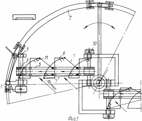
FIG. 1 shows a schematic diagram of a wind power plant, a top view.
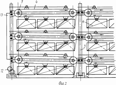
FIG. 2 - the same, side view.
The wind power plant comprises a peripheral support 1 contacting the circular rail 2, a rotatable central support 3 and a conveyor 4 connecting the supports 1 and 3 and including the paddles 6 pivoted on the endless power circuits 5 with control mechanisms 7 covered by chains 5 gears 8 fixed On parallel shafts 9, and an electric generator 10 kinematically connected to one of the shafts 9.
The installation is additionally equipped with conveyors 4 and one peripheral support 1, each support 1 and 3 is made in the form of a vertical post, all transporters 4 are mounted on supports 1 and 3 in a girdle and symmetrical relation to the central post 3 and the latter is connected to two peripheral posts 1 by means of conveyors 4.
In addition, the blade control mechanism 7 is made in the form of a cable system through which the peripheral part of each blade 6 is connected to the hinge of one of the adjacent blades 6, and each blade 6 is concave from the windward side provided with the ribs 11.
The installation is provided with a forced correction device 12 and stabilizers 13 with respect to the flow direction.
INSTALLATION WORKS AS FOLLOWING
With the aid of the device 12, the conveyors 4 are installed in such a way that the flow is directed perpendicularly to the blades 6 and the blades 6 move together with the chains 5, causing the electric generators 10 to rotate. When moving towards the flow, the blades 6 are folded by the cable system 7, which reduces the fan losses . When the wind direction is changed, the device 12 guides the posts 1, 3 and together with the conveyors 4 to the direction of flow along the rail 2, which allows maximum use of wind energy.
CLAIM
1. A WIND POWER PLANT comprising a peripheral support in contact with a circular rail, a rotatable central support and a conveyor connecting the supports and including pivots mounted on endless power circuits with control mechanisms, chain-covered gears fixed to parallel shafts, and an electric generator kinematically coupled With one of the shafts, differing in that, in order to increase the efficiency, the unit is equipped with additional conveyors, each of which has hinged arms on endless power chains with control mechanisms, chain-covered gears fixed to parallel shafts and an electric generator kinematically connected With one of the shafts and an additional peripheral support, each support is made in the form of a vertical post, the conveyors are mounted on the bearings in a girdle and symmetrical relation to the central post, and the latter is connected to two peripheral posts by means of conveyors, and the axes of the blades are located at an angle to the axis of the gears .
2. An installation according to claim 1, characterized in that the blade control mechanism is in the form of a cable system connecting the peripheral part of each blade to the hinge of one of the adjacent blades.
3. An installation according to claim 1, characterized in that each blade is provided with ribs that are concave from the windward side, and the fins are placed on the latter.
print version
Date of publication 11.02.2007gg
![]()

Comments
When commenting on, remember that the content and tone of your message can hurt the feelings of real people, show respect and tolerance to your interlocutors even if you do not share their opinion, your behavior in the conditions of freedom of expression and anonymity provided by the Internet, changes Not only virtual, but also the real world. All comments are hidden from the index, spam is controlled.