| section Home
Production, Amateur Radio amateur Model aircraft, rocket- Useful, entertaining |
Stealth master
Electronics Physics Technologies invention |
space Mystery
Earth Mysteries Secrets of the Ocean Stealth section Map |
  |
| Use of material is permitted for reference (for websites - hyperlinks) | |||
Navigation: => |
Home / Products Patents / In the section of the catalog / back / |
|
INVENTION
Russian Federation Patent RU2218651
![]()
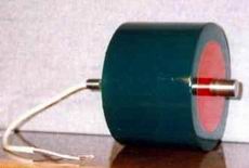
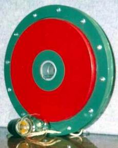
GENERATOR FOR Belashova low speed wind turbines
Name of the inventor:
The name of the patentee: Alexey Balashov
Address for correspondence: 109559, Moscow, Tikhoretsky Boulevard, 14, building 2, kv.63, A.N.Belashovu
Starting date of the patent: 2000.10.18
The invention relates to the field of electrical engineering, namely to designs of universal electric machines modular, designed for use in all sectors of the economy as a direct current generator, single-phase or multi-phase AC generator, the machine DC, single-phase or multi-phase AC motor, welding machine AC or DC power. The essence of the invention is that the universal electrical machine is an even or odd number of modules. Each machine module comprises a stator, a rotor with magnetic systems and magnetic cores, multi-turn stator with windings, housing a closed collector, detachable shaft, conductive brush, an electronic switch, the automatic tracking and control elements rolling or sliding. According to the invention, and each module has an opening closed collector for connection and transfer torque to the removable shaft. The rotor and stator interact through an even or odd number of sliding or rolling elements. The rotor of each module consists of two disks, each provided with a cylindrical projection with a hole for detachable engagement with the shaft, and a stator module is designed as a bushing, which is placed inside the stator yoke. The technical result is to provide cost-effective, energy-efficient electric cars, capable of working from any source of voltage or current.
DESCRIPTION OF THE INVENTION
The invention relates to the construction of the universal electrical machine Belashova and is intended for use as generator of direct current, single-phase or multi-phase AC generator, the machine dc single-phase or multiphase AC motor welder AC or DC current measuring device, a voltage converter and a current , voltage regulator, etc. for use in all sectors of the economy and can be used for military purposes.
Known collector Belashova containing insulating sleeve with a closed contact between the plates, which are electrically connected to the slip rings, the electronic switch, conductive brushes and plug connection. See Russian patent 2073296, Cl. H 02 K 13/14, 27/22 - analogue.
Known Belashova generator comprising an inductor with permanent magnets, which interact with the multi-turn windings of a non-magnetic armature capable of producing several different kinds simultaneously emf. The modular design of the generator consists of identical interchangeable parts and components. See Russian patent 2025871, Cl. H 02 K 21/00 - analogue.
Known universal electrical machine Belashova comprising a body with an even or odd number of modules, each module includes a rotor magnet systems and the magnetic cores, a stator with multi-turn windings closed collector contact plates, the conductive brush current electronic switch, an automatic monitoring and regulation , rolling or sliding elements. See Russian patent 2118036, Cl. H 02 K 23/54 - prototype.
The purpose of the invention - to increase the efficiency, safety and reliability of electric machines. Extend the functionality and scope of universal modular electric machines. Apply system for automatic monitoring and control of the operation of the machine from a variety of sources unknown voltage. Simplify and improve the technology of manufacturing and repair of universal electric cars, with full interchangeability of parts and components. To ensure that the consumer himself, of separate modules, the machine was able to gather a given power at a predetermined voltage and a predetermined number of revolutions.
The essence of the technical solutions lies in the fact that the universal electrical machine comprises a housing with an even or odd number of modules. Each machine module includes a rotor, a stator, a closed manifold with contact plates, conductive brush current rolling elements. The rotor module consists of two disks, each provided with a cylindrical projection with a hole for detachable engagement with the shaft. On each disc rotor yoke and magnets are placed with the lock. The stator module is designed as a bushing, which is placed inside the stator yoke, and the stator module interacts with the rotor module over an even or odd number of sliding or rolling elements. stator yoke includes a multiturn coil, external and internal reinforcing ribs, which are placed on racks and stator closed diamagnetic screens. The stator, a rotor and a closed car collector module contains heat exchange system. Multiturn stator winding through a closed collector contact plates, conductive brush current electronic switch connected with automatic tracking and control system. The upper and lower parts of the body interact with detachable shaft through other rolling elements. Each module is closed and the reservoir has a hole for connection and transfer torque to a removable shaft, wherein the stator yoke is made of diamagnetic or paramagnetic material.
 |
 |
 |
 |
 |
 |
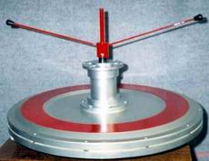
1 shows a general view of a universal electrical machine.
Figure 2 shows a section A-A of the machine module.
Figure 3 shows a section B-B of the machine module.
4 shows a sectional view of a single-phase machine module.
5 shows a sectional view of the closed collector machine.
6 is a circuit diagram of the universal electrical machine.
Universal electric machine 1 comprises an even or odd number of identical modules 1. Each module has a connector for supply voltage 2, a closed manifold 3, which has a connector for the supply and discharge voltage 4, detachable shaft 5. Each module is closed and the universal manifold electric machine has a hole for connection and transfer torque to the shaft 5. The removable module opening, the opening of the closed reservoir and a removable shaft may have different geometric shapes compound torques. For example, the module opening and a removable shaft 5 have the form of hexagon 6, FIG. 2. The module consists of a rotor disk 7 and 8. Each of the rotor disc drive is provided with a cylindrical projection with an opening for interaction with detachable shaft 5. The disc rotor 7 positioned magnetic magnets 30 and 11 having a retainer 12. On the rotor disk 8 placed magnetic circuit 13 and magnets 14 having the retainer 15. The retainer 12 and the retainer 15 must be made of high strength diamagnetic material, for example of a titanium alloy. The stator module is in the form of plugs 16, 17, which is placed inside the stator yoke 20, and the module communicates with the stator unit through the rotor even or odd number of sliding or rolling elements 18, 19. Inside the stator yoke 20 is positioned even or odd number of multiturn windings 21 even or odd number of phases. Moreover, the stator yoke 20 is made of diamagnetic or paramagnetic material. Magnetic multiturn otbmotki 20 and 21 are closed diamagnetic shields 22, 23. The stator 20 includes a magnetic external stiffeners 24 with internal reinforcing ribs 25, which are placed in racks 26 and 27. The even or odd number of models universal electrical machine is arranged between the upper and lower part of the body . The upper part of the housing 28 interacts with a removable shaft 5 via rolling elements 29. Between the modules universal electrical machine has pads 30 and the system of heat transfer 31. The system of heat 31 is formed in the form of intermediate liners, gaskets, stoppers or radiators of various shapes and is connected with the upper part of the housing 28 and the bottom of the housing 32, 3, the fixing elements 33. The lower part of the housing 32 communicates with removable shaft 5 through the rolling elements 34. Removable shaft 5 can transmit torque to the module through the hole even or odd number of key connection 35. The stator sleeves 16, 17 may interact with cylindrical projections through one rolling element bearing rotor disks 7, 8, 36. Closed collector 3 consists of an even or odd number of contact plates 42, 43, 44, 45, conductive rings 38, 39, 40, 41, which are located on a dielectric sleeve 37. The first phase of the module has an even or odd number of contact plates 42, which are electrically connected to current conductive ring 38, and an even or odd number of closed contact plates 43, which are electrically connected to the conductive ring current module 39. The second phase has an even or odd number of closed contact plates 44, which are electrically connected to the conductive ring 40, and an even or odd number of closed contact plates 45, which are electrically connected to the conductive ring 41 is even or odd number of stator phases have a closed manifold that podpryazhennoy electrically connected to the brush 46 disposed within the housing of the brush mechanism 47. The conductive ring current of the first phase 38 is electrically connected to the brush 48. The conductive podpryazhennoy ring current of the first phase 39 is electrically connected to the brush 49. podpryazhennoy conductive ring of the second phase 40 is electrically connected to podpryazhennoy brush 50. The conductive ring of the second phase current 41 is electrically connected to the brush 51. The closed podpryazhennoy manifold 3 is fixed to the shaft 52 a nut 53 having a stopper device 54. The brush mechanism 47, and a closed collector 3 is located in the manifold body 55 which is fixed to the bottom of the housing 32 fasteners 56. The multi-turn winding of the first phase of the multi-turn coils 21 are identical to the second phase 57. The module 4, may be single phase and have diamagnetic magnetic core 20, inside of which there are multiturn winding 21. For large diameters module universal electrical machine cylindrical protrusions of the rotor disks They should be replaced with cylindrical sleeves, and structural rigidity for a cylindrical rotor sleeve 7 should fit snugly into another cylindrical rotor sleeve 8. as a diamagnetic material a single-phase stator yoke 20 may be made of a durable dielectric. For AC sinusoidal emf rotor yokes 11, 13 to be manufactured in the form of discs. For pulse signal rotor emf rectangular yokes 11, 13 to be manufactured in sections. A removable manifold hole 58 and the shaft reservoir 52 may take the form of a square, Figure 5. Phase contact plates 42 are electrically connected to the collector ring 59 and bridge 60 current conductive ring 38 and the contact plate 43 of the first phase are electrically coupled to collector ring 61, the conductive bridge 62 and the current ring 39. The contact plate 44 of the second phase are electrically coupled to collector ring 63, bridge 64 and conductive ring 40 and the contact plate 45 of the second phase are electrically connected to the collector ring 65, bridge 66 and conductive ring 41. The closed manifold 3, 6, interacts with podpryazhennoy brush 46, the brush 67 and podpryazhennoy source 68. The electronic power of the first phase control switch 69 includes a gate electrode 70 of the thyristor 71, the gate electrode 72 of the thyristor 73, the gate electrode 74 of the thyristor 75, the gate electrode 76 of the thyristor 77. The second phase of the electronic control switch 78 includes a gate electrode 79 of the thyristor 80, the gate electrode 81 SCR 82, the gate electrode 83 of the thyristor 84 and the gate electrode 85 of the thyristor 86.
Moreover module universal electrical machine may be designed as a generator, generating EMF of various kinds, an AC generator having an even or odd number of phases, DC generator of the AC motor, having an even or odd number of phases of the DC machine, welding permanent unit or alternating current measuring device and a current-voltage converter, the voltage regulator. machine module may include an even or odd number of stators and rotors in a housing. machine drive system can be made from permanent magnets, electromagnets or a combination of the joint and maintain an even or odd number of magnetic poles and cores, which can be closed diamagnetic screens. The excitation system can be located on the stator or the rotor of the machine. If the machine has an electromagnetic excitation, while multiturn windings of the excitation system can have parallel, serial or mixed electrical connection. The rotor, a stator and a removable reservoir module contains heat exchange system. At high speeds the machine, the electronic switch can be made with transistors. Closed collector can be controlled by an independent voltage source, and having an electronic switch in its construction. automatic tracking and control system can be made a separate unit, contain information transmission device in the information-processing machine having a current-measuring device and the device of protection against overcurrent.
RUNNING GENERATOR low speed Belashova FOLLOWS
Low-speed universal electric cars small capacity contain multiturn windings of the first phase 21 and multiturn windings of the second phase 57, which have a large number of turns, a large internal resistance and consume a small amount of current that allows to apply the control current to the multiturn coil of each phase directly from the power source 68 through a closed 3. The current collector of positive polarity of the power supply terminal 68 is supplied to podpryazhennuyu brush 67, the contact plate 42 of the closed collector 3, the collector ring 59, current conducting ring 38, podpryazhennuyu brush 48 and at the beginning of the first phase of multi-turn coils 21. Then the current of positive polarity end of multiturn windings of the first phase 23 is fed to podpryazhennuyu brush 49, current conducting ring 39, the ring collector 61, the contact plate 43 of a closed reservoir 3 podpryazhennuyu brush 46 and a negative power source terminal 68. The current flowing at the first phase of multiturn windings begins to interact with permanent magnet of the excitation system 11, 14 and create a torque that moves the rotor unit at the left hand rule in another position. The current positive polarity of the power supply terminal 68 is supplied to podpryazhennuyu brush 67, the contact plate 44 of the closed collector 3, ring collector 63-conductive ring 40, podpryazhennuyu brush 50 and the end of the multi-turn coils of the second phase 57. Further, the current of positive polarity since the beginning of multi-turn coils second phase 57 is fed to podpryazhennuyu brush 51, current conducting ring 41, the ring collector 65, the contact plate 45 of a closed reservoir 3 podpryazhennuyu brush 46 and a negative power source terminal 68. The current flowing through the multiturn windings of the second phase begins to interact with the permanent magnet system drive 11, 14 and create a torque that moves the rotor unit at the left hand rule in another position. The current positive polarity of the power supply terminal 68 is supplied to podpryazhennuyu brush 67, the contact plate 43 of the closed collector 3, ring collector 61-conductive ring 39, podpryazhennuyu brush 49 and the end of the first phase of multiturn windings 21. Further current positive polarity since the beginning of the first multi-turn coils phase podpryazhennuyu 21 enters the brush 48, current conducting ring 38, the ring collector 59, the contact plate 42 of a closed reservoir 3 podpryazhennuyu brush 46 and a negative power source terminal 68. The current flowing at the first phase of multiturn windings 21 begins to interact with the permanent magnet system drive 11, 14 and create a torque that moves the rotor unit at the left hand rule in another position. The current positive polarity of the power supply terminal 68 is supplied to podpryazhennuyu brush 67, the contact plate 45 of the closed collector 3, ring collector 65-conductive ring 41, podpryazhennuyu brush 51 and the beginning of the multi-turn coils, the second phase 57. Next, the current of positive polarity at the end of multi-turn coils the second phase 57 is fed to podpryazhennuyu brush 50, current conducting ring 40, ring collector 63, the contact plate 44 of the closed collector 3, podpryazhennuyu brush 46 and a negative power supply terminal 68. The current alternately flows through the windings of the first phase of the multi-turn 21 and then by the second multi-turn coils phase 57 interacts with permanent magnet excitation system 11, 14 and creates a constant rotating movement of the machine rotor. When the polarity of the change in the podpryazhennyh brushes 46 and 67 of the machine is in reverse mode. Speed universal electric cars of high power, which can carry a current of several hundred amperes, must work with the electronic switch of the first phase 69 and an electronic switch of the second phase 78, and the control voltage on podpryazhennyh brushes 46, 67 can be self-contained and powered by an independent source of constant voltage up to 12 V and current of 50 mA. Negative polarity current from the power source terminal 68 is supplied to podpryazhennuyu brush 46, the contact plate 43 of a closed reservoir 3, the manifold ring 61, conductive ring current 39 podpryazhennuyu brush 49, control electrodes 74, 76 which close the thyristors 75, 76. The current positive polarity from the power source terminal 68 is supplied to podpryazhennuyu brush 67, the contact plate 42 of a closed reservoir 3, the ring collector 59, the conducting current ring 38 podpryazhennuyu brush 48, control electrodes 70, 72 which open thyristors 71, 73 for passing current through multiturn windings of the first 21 from the end phase windings to their top. The current flowing through the first phase of multiturn windings begins to interact with the permanent magnet of the excitation system 11, 14 and create a torque that moves the rotor unit at the left hand rule in another position. The current negative polarity of the power supply terminal 68 is supplied to podpryazhennuyu brush 46, the contact plate 45 of the closed collector 3, ring collector 65-conductive ring 41, podpryazhennuyu brush 51, the control electrodes 79, 81, which cover the thyristors 80, 82. The current positive polarity voltage 68 source terminal is fed to podpryazhennuyu brush 67, the contact plate 44 of a closed reservoir 3, the ring collector 63, the conducting current ring 40 podpryazhennuyu brush 50, control electrodes 83, 85 which open thyristors 84, 86 for passing on multiturn windings of the current second 57 from the beginning of the phase windings to their end. The current flowing through the multiturn windings of the second phase begins to interact with the permanent magnet of the excitation system 11, 14 and create a torque that moves the rotor unit at the left hand rule in another position. Negative polarity current from the power source terminal 68 is supplied to podpryazhennuyu brush 46, the contact plate 42 of a closed reservoir 3, the manifold ring 59, conductive ring 38 current, podpryazhennuyu brush 48, control electrodes 70, 72 which close the thyristors 71, 73. The current positive polarity from the power source terminal 68 is supplied to podpryazhennuyu brush 67, the contact plate 43 of a closed reservoir 3, the ring collector 61, a ring 39 of conducting current podpryazhennuyu brush 49, control electrodes 74, 76 which open thyristors 75, 77 for passing current through multiturn windings of the first 21 from the beginning of the phase windings to their end. The current flowing through the first phase of multiturn windings begins to interact with the permanent magnet of the excitation system 11, 14 and create a torque that moves the rotor unit at the left hand rule in another position. Negative polarity current from the power source terminal 68 is supplied to podpryazhennuyu brush 46, the contact plate 44 of a closed reservoir 3, the manifold ring 63, conductive ring 40 current, podpryazhennuyu brush 50, control electrodes 83, 85, which close the thyristors 84, 86. The current positive polarity from terminal power source 68 is supplied to podpryazhennuyu brush 67, the contact plate 45 of the closed collector 3, ring collector 65, a conductive current ring 41 podpryazhennuyu brush 51, the control electrodes 79, 81 that open thyristors 80, 82 for passing current through the multi-turn coils of the second 57 from the end of phase windings to their top. The current alternately flowing through multiturn windings of the first phase 21 and second phase of multiturn windings 57 interacts with permanent magnet excitation system 11, 14 and generates on the rotor rotating machine permanent motion. Universal electric vehicle is powered by the AC as developing engine torque independent of the current work in the stator winding and the magnetic flux of the rotor excitation system poles. module stator and rotor current does not change its direction while changing the direction of the current in the windings of the stator coils and the magnetic flux of the rotor excitation system poles. the rotor excitation system 11, 14, the universal electrical machine can consist of electromagnets. Versatile electric machine from the AC voltage source resembles the operation of the machine from a DC source. The difference is that each positive half cycle of the sinusoidal voltage alternately passes through the contact plate of the closed collector ring manifold podpryazhennye brushes, working multiturn windings of the first phase 21, the electromagnets of the rotor excitation system 11, 14 and then through the working multiturn windings of the second phase 57 and the electromagnets rotor drive system 11, 14.
Universal electric machine having a stator of a diamagnetic (dielectric) material have advantages over large electrical machines in which the stator is made of paramagnetic (ferromagnetic) material, namely:
- There may be not only a sinusoidal AC signal, and a rectangular pulse voltage signal and current.
- Have a large area of the rotor drive system.
- Have a good cooling.
- Have a reliable insulation resistance of multi-turn coils.
- There may be an automatic monitoring and regulation, which is able to change the parameters of the machine during operation.
- Can work without a closed reservoir.
- Can easily be adjusted for current and voltage.
- Can automatically detect the electromotive force of the incoming signal.
- Can be made from a few watts to many hundreds of kW.
- May simultaneously issue a permanent emf and emf AC any number of phases.
- There may be a threshold of sensitivity of less than one volt.
- May rotate at less than one revolution per minute.
- Can work on one or more independent sources of different voltage and current, and in the southern countries from solar energy.
- No hysteresis loss.
- No eddy current losses.
- No loss reactance of the armature.
The invention allows to create a new line of universal, cost-effective, energy-efficient electric cars, capable to determine the incoming current, voltage, and run from any unknown user voltage or current source. machine module can be used as a direct current machine, single-phase or multiphase AC motor, a DC generator, a single-phase or multiphase alternating current generator, welder AC or DC voltage or current measuring device or transducer. At the same time the user can himself from individual modules to complete the car of any power and any tension.
 |
 |
 |
CLAIM
1. Universal electric machine, comprising a housing with an even or odd number of modules, each module includes a rotor magnetic circuits and magnetic systems, with a multi-turn stator windings closed collector contact plates, the conductive brush current electronic switch, and the automatic tracking adjustment , rolling elements, characterized in that in each module the rotor consists of two discs, each provided with a cylindrical projection with a hole for engagement with a removable shaft, the module stator is made in the form of sleeves, inside which is placed a stator magnetic circuit, wherein a module stator interacts with the rotor module by an even or odd number of rolling elements or sliding magnetic stator includes external and internal stiffening ribs, which are placed on racks, magnetic and multiturn stator winding closed diamagnetic screens on each rotor disc placed magnetic conductors and magnets, having clamp stator , a rotor and a closed collector modules comprise a system of heat transfer, the upper and lower part of the housing interacting with the removable shaft through other rolling elements, each module, and a closed collector having an opening for connection and transfer torque to a removable shaft, wherein the magnetic circuit of the stator is made of diamagnetic or paramagnetic material.
2. Machine according to claim 1, characterized in that the machine module is an AC generator having an even or odd number of phases.
3. Machine according to claim 1, characterized in that the machine unit is configured as a direct current generator.
4. Machine according to claim 1, characterized in that the machine unit is configured as an AC motor having an even or odd number of phases.
5. The machine according to claim 1, characterized in that the machine unit is configured as a DC machine.
6. Machine according to claim 1, characterized in that the machine unit is configured as a welding unit AC or DC.
7. The machine according to claim 1, characterized in that the machine unit is configured as a measuring device.
8. Machine according to claim 1, characterized in that the machine unit is configured as a voltage and a current converter.
9. Machine according to claim 1, characterized in that the machine unit is configured as a voltage stabilizer.
10. Machine according to claim 1, characterized in that the machine module comprises an even or odd number of rotors and stators.
11. Machine according to claim 1, characterized in that it comprises an even or odd number of phases.
12. Machine according to claim 1, characterized in that several generates emf various kinds.
13. Machine according to claim 1, characterized in that the electronic control is configured to switch transistors.
14. Machine according to claim 1, wherein said automatic tracking control system and is designed as a current measuring device.
15. Machine according to claim 1, wherein said automatic tracking control system and equipped with a device for protection against current overloads.
16. Machine according to claim 1, characterized in that the automatic tracking and management system further comprises a data transmission apparatus in the information-processing machine.
17. Machine according to claim 1, wherein said automatic tracking control system and made a separate unit.
print version
Publication date 24.03.2007gg
![]()

Comments
Commenting, keep in mind that the content and the tone of your messages can hurt the feelings of real people, show respect and tolerance to his interlocutors, even if you do not share their opinion, your behavior in terms of freedom of speech and anonymity offered by the Internet, is changing not only virtual, but real world. All comments are hidden from the index, spam control.