
| Start of section
Production, amateur Radio amateurs Aircraft model, rocket-model Useful, entertaining |
Stealth Master
Electronics Physics Technologies Inventions |
Secrets of the cosmos
Secrets of the Earth Secrets of the Ocean Tricks Map of section |
  |
| Use of the site materials is allowed subject to the link (for websites - hyperlinks) | |||
Navigation: => |
Home / Patent catalog / Catalog section / Back / |
|
INVENTION
Patent of the Russian Federation RU2046997
![]()
AUTONOMOUS VERTICAL-AXIAL WIND-INSTALLATION
The name of the inventor: Platonov E.N .; Fridman B.M.
The name of the patent holder: "Raduga" Engineering Design Bureau
Address for correspondence:
The effective date of the patent: 1992.04.21
Use: in wind power. SUMMARY OF THE INVENTION: The autonomous vertical-axial wind-driven installation comprises a wind wheel 1 made in the form of a pipe 2 with fixed blades 3 fixed in the rotation supports 4 on the base 5 and connected through the rotation transmission mechanism 6 to the generator 7, the base 5 being made of Two parts 8 and 9, and the base parts are connected to each other by a two-stage hinge 10, one part 8 being made in the form of a rod 11, the upper part of which is coaxially located inside the wind wheel tube 2, and the lower part is provided with a float 12 covering the rod 11 and positioned above the hinge, Wherein the second base part 9 is provided with a trough 14 filled with a liquid in which a float 12 is placed and the generator 7 is fixed to the float.
DESCRIPTION OF THE INVENTION
The invention relates to wind energy and can be used in the creation of wind power plants operating in autonomous systems.
Vertical axial wind installations, such as the Darjeel type, are known (US Patent No. 1,835,018).
The closest to the invention is a wind turbine (U.S. Patent No. 4,630,996) comprising a wind wheel made in the form of a pipe with fixed blades mounted in the rotation supports on the base and connected through a rotation transmission mechanism with a generator and a base made of two parts.
Disadvantages of the prototype when it is used in autonomous systems are the complexity of reconciling the parameters of the wind farm and the consumer, which requires the use of a generator whose power can many times exceed the power of the consumer of energy and the use of special devices to dissipate excess energy.
The aim of the invention is to improve the technical and economic parameters of the installation by matching its parameters with the parameters of the consumer.
For this purpose, in an autonomous vertical-axial wind-driven installation comprising a wind wheel made in the form of a pipe with fixed blades fixed in the rotation supports on the base and connected through a rotation transmission mechanism with a generator and a base made of two parts, the base portions are connected between A one-piece joint is made in the form of a rod, the upper part of which is coaxially located inside the wind wheel tube, and the lower part is provided with a float covering the rod and located above the hinge, the second part of the base being provided with a trough filled with a liquid in which the float is placed and The generator is fixed to the float.
 |
 |
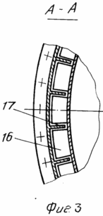 |
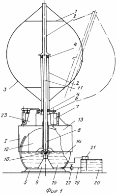
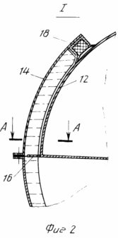
1 shows a proposed installation; In Fig. 2, the node I in Fig. 1; FIG. 3 shows a section AA in FIG. 2. FIG.
The autonomous vertical-axial wind installation consists of a wind wheel 1 made in the form of a tube 2 with fixed blades 3 fixedly mounted on it. The wind wheel 1 is fixed in the rotation supports 4 on the base 5 and connected through the rotation transmission mechanism 6 to the generator 7. The base 5 is made of two parts 8 and 9 connected to each other by a two-stage hinge 10. The base part 8 is in the form of a rod 11, the upper part of which is coaxially located inside the wind wheel tube 2, and the lower part is provided with a float 12 above the hinge with a lid 13 enclosing the rod 11. The second base part 9 Is provided with a trough 14 filled with a liquid 15 in which a float 12 is placed. The generator 7 is fixed to the lid 13 of the float 12. The hydrodynamic surfaces 16 are mounted on the float 12, and the trough 14 is provided with meridian fins 17 and a seal 18. For filling the trough with a liquid and draining it A special system 19 including a reservoir 20, a pump 21 and a crane 22. To stop and hold the rotation of the wind wheel 1, the unit is provided with a braking device 23.
INSTALLATION WORKS AS FOLLOWING
When the air flow interacts with the wind turbine generator 1, which is previously untwisted, for example, the aerodynamic forces arising on its blades 3 create a torque which, through the rotation transmission mechanism 6, is transmitted to the shaft of the generator 7 generating electrical energy. The aerodynamic forces simultaneously create a heeling moment, which leads to the appearance of the nutation angle of the wind wheel axis 1. The action of the heeling moment on the rotating wind wheel 1 causes simultaneous precession of the axis of the latter. The degrees of freedom corresponding to the nutation and precession angles are provided by the hinge 10. The appearance of the nutation angle of the wind wheel axis in the wind plane leads to a decrease in the output power. The heeling moment is counterbalanced by the moment of the hydrostatic force applied to the float 12. The magnitude of the hydrostatic force moment is determined by the size and shape of the float, the level and specific gravity of the fluid and varies as a function of the nutation angle. Damping of oscillations during transient processes occurs due to a change in the drag force of the wind wheel 1 with a change in the precession angle and due to the throttling of the liquid through the gaps between the walls of the trough 14 with the fins 17 and the hydrodynamic surfaces 16. The sealing of the liquid from the trough is prevented by the seal 18.
CLAIM
AUTONOMOUS VERTICALLY-CENTRAL WINDING SYSTEM comprising a wind wheel made in the form of a pipe with fixed blades mounted on it, fixed in rotation supports on the base and connected through a rotation transmission mechanism with a generator, the base being made of two parts, characterized in that the base parts are connected A one-piece joint is made in the form of a rod, the upper part of which is coaxially located in the wind wheel tube, and the lower part is provided with a float that surrounds the rod and is located above the hinge, the second part of the base being provided with a trough filled with a liquid in which the float is placed, And the generator is fixed to the float.
print version
Date of publication 24.03.2007gg
![]()

Comments
When commenting on, remember that the content and tone of your message can hurt the feelings of real people, show respect and tolerance to your interlocutors even if you do not share their opinion, your behavior in the conditions of freedom of expression and anonymity provided by the Internet, changes Not only virtual, but also the real world. All comments are hidden from the index, spam is controlled.