| Start of section
Production, amateur Radio amateurs Aircraft model, rocket-model Useful, entertaining |
Stealth Master
Electronics Physics Technologies Inventions |
Secrets of the cosmos
Secrets of the Earth Secrets of the Ocean Tricks Map of section |
  |
| Use of the site materials is allowed subject to the link (for websites - hyperlinks) | |||
Navigation: => |
Home / Patent catalog / Catalog section / Back / |
|
INVENTION
Patent of the Russian Federation RU2049265
![]()
Windmill
The name of the inventor: Alexey Viktorovich Konichev [BY]; Konichev Sergey Alexeevich [BY]
The name of the patent holder: Aleksey V. Konichev (BY)
Address for correspondence:
The effective date of the patent: 1992.02.20
Use: in stationary and transport wind turbines. SUMMARY OF THE INVENTION: The wind turbine comprises a vertical tubular shaft 5, the upper end of which is located in the bearing of the crosspiece 9, and the lower end is kinematically connected to the electric current generator 13, the obliquely arranged tubular concentric rims 6 with radial spokes 4, the ends of which are fixed to the shaft 5 and peripheral rims 6 , The blades 2, the rings 25, the rings 25 surrounding the shaft 5, the links 21, the latches 26 and the mechanism 14 for automatically adjusting the rotation angle of the blades 2. Each blade 2 is made of a planar rectangular shape with a cut off bottom corner at the edge facing the shaft 5. The blades 2 are pivoted Spokes 4 with the formation of a gap between the shaft 5 and the cut edge. In the gaps, there are rings 25 connected by rods 21 to the rotation angle adjustment mechanism 14 of the blades 2. The swivel attachment of the blades 2 with the upper edge or on the axes set above the middle line of each blade is provided, the peripheral rims 6 being connected by vertical tubular posts.
DESCRIPTION OF THE INVENTION
The invention relates to wind energy and can be used in stationary and transport wind turbines of various purposes and capacities.
A wind turbine is known [1] comprising a wind wheel with a hub and fixed rotary inclined blades with trunnions connected to rollers equipped with bevel gears kinematically connected to a central gear, a gear train and other gears connected to a power take-off device and a weathervane with Mast.
The disadvantages of this wind turbine are: low efficiency, complexity and labor-intensive manufacturing, a large mass.
The closest proposed solution is the basic wind turbine [2] chosen for the prototype containing a wind wheel with curved blades mounted on a vertical shaft with an upper bearing flange fixed to the support located on the base and shielding blades and swivel shields.
Disadvantages of the basic wind turbine are as follows:
Low efficiency, since the wind wheel with curved blades has great resistance to rotation against the counter-flow, almost equal to the force of rotation; A large mass, since the adjustment of the speed is achieved with the help of an additional four pillars and swivel shields, which cost twice as much metal as the windrower with blades; There is no mechanism for reliable speed control, since even a weak wind can completely block the way of the wind wheel to the blades, and the windmill will stop;
There is no mechanism for returning the shields to their original position;
Increase wind load on the design of the wind turbine in the storm winds, since the shields are closed, and the cross-sectional area of the construction with the opposing wind increases;
Low unit power.
The purpose of the invention is to increase the reliability and economy in the operation of the wind turbine by automatically changing the angle of the blade inclination to the direction of the wind, which automatically adjusts the speed of the windmill during storms and increases wind strength; Increasing the efficiency of the wind turbine by reducing the resistance when moving the blade to the counterflow of air almost to zero, since the blades are self-aligned parallel to the direction of the wind, reducing the mass and dimensions per unit of power, increasing the methods for controlling the operation of the windmill: automatic, remote from the control panel, manual; Reduction of wind load during storms and wind strengthening, since the blades are installed parallel to the wind, the windmill stops and the area of resistance to wind load decreases; High unit power.
The aim is achieved by the fact that the windmill is equipped with rectangular blades, one of the corners of which is cut out in the lower part of the mast adjacent to the mast, and the blades are connected by the upper edge to the radial cross-pieces of the upper wind wheel, and the lower edge rests at an angle to the bottom of the lower wind wheel.
In the design of the windmill, several methods for controlling the windmill operation are provided, automatic, remote, manual.
Automatic control of the windmill and speed control with wind amplification are carried out using a centrifugal regulator, in which, with an increase in the number of revolutions, the counterweights are dispersed by the action of centrifugal forces and through hinges and thrusts act on control rings connected by longitudinal rods, Their upward, thereby reducing the angle of the counterflow of air, therefore, the blade area and revolutions decrease, with stormy winds, the blades rise parallel to the wind wheel, and the windmill stops and the upper position of the blades is fixed by the latch.
For remote control of the windmill, a remote control mechanism is implemented which, when turned on by the operator, acts on the inner beaker and moves it upwards, lifts the weights of the counterweights and the control rings connected by the rods act on the blades and lift them upward, reducing the angle to the counterflow of air, Blades, and turns decrease.
Comparative analysis with the prototype shows that in the proposed wind turbine blades of the wind wheel are rectangular with one cut angle in the lower part adjacent to the mast, the upper edges of the blades being connected to the radial cross-pieces of the upper wind wheel, and the lower edge at the calculated angle rest on the bottom of the lower wind wheel.
In addition, the windmill is equipped with a universal control system that allows its operation in three modes: automatic, remote from the operator's control panel and manual, and for all control systems of the executive mechanism regulating the speed of the windmill with increasing wind speed, a stop in the storm is produced by this alone Mechanism acting simultaneously on all the blades. These control rings, installed with the ability to move along the mast, connected together by rods, located in each wind wheel in the angular notch of each blade.
In automatic control mode, a centrifugal regulator is used for this purpose, which, when the speed is increased beyond the calculated value through the hinges and links, interacts with the speed control mechanism, moves it up the mast and at the same time lifts the blades, thereby reducing the useful area of the force of the wind flow On the blade, as a result, the rotation torque decreases, and consequently the wind turbine speed decreases, and in the case of storm winds, the speed control mechanism raises the blades parallel to the wind wheel, the torque decreases to zero, the windmill stops and the blades in the upper position are latched.
When the operator is operated remotely, the mechanism for adjusting the speed and moving it up and down the mast is effected by turning on an electric motor that rotates a pair of gears and a female thread that interacts with the external thread of the inner cup, as a result of which the latter moves along the pin along the rails , And the revolutions decrease, they increase. With manual control, the movement of the speed control mechanism is carried out by rotating the same gears and cups, but with the help of a handle.
As can be seen from the above, the design of the windmill adopted for the prototype has a lower efficiency compared to the proposed one.
 |
 |
 | |
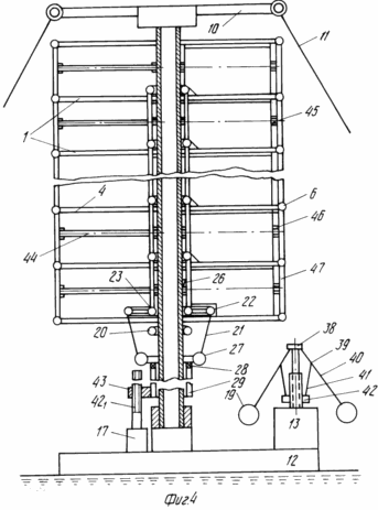 |
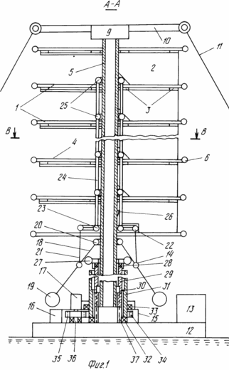
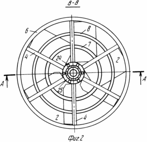
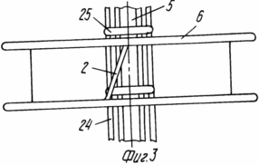
FIG. 1 shows a windmill, section AA in FIG. 2; 2 is a cross-sectional view taken along line B-B in FIG. 1; 3 is a front view of a wind wheel; 4, a high power wind turbine. The wind turbine contains wind wheels 1 with rectangular blades 2 fixed at the top on hinges 3 to radical spokes 4 fixed one end to the tubular shaft 5 and the other to the tubular rim 6. On the upper part of the mast the bearing unit 9 is mounted with the crosspiece 10 to the ends of which Rigid fastening of the extensions 11, the lower part of the shaft 5 is installed in the thrust and radial bearings, and between the bearings a pinion is mounted which is meshed with gears of the reduction gear 12, the output shaft of the reducer is connected to a power take-off device 13, which can be a generator, pump, E. The wind turbine also contains an automatic adjustment device for the 14th speed and automatic shutdown of the turbine, and there is also a remote control mechanism 15 that is activated from the operator's console by means of an electromagnet 16 that includes a power take-off from the reducer or an electric motor 17. A centrifugal regulator 18, which consists of counterweights 19, hinges 20, rods 21 connected to rings 22 rigidly connected to inner ring 23 which, by means of rods 24, is connected by their control rings 25 located in subsequent windscreens, the latch 26. |
The remote control mechanism 15 consists of a tubular ring 27 mounted on the bearings 28 of the inner cup 29 with external threads and guides 30 serving for a directed linear motion along the grooves of the stationary pin 37, an outer threaded cup 31 with an internal thread mounted on the thrust bearing 32 and a radial 33 , A pinion 34 is fixedly fixed to it at the bottom, which is in engagement with a pinion 35 rigidly fixed to the shaft of the electric motor 17; on the other side of the pinion 35, a shaft 36 is mounted which, by means of a sliding sleeve (not shown), controlled by the electromagnet 16, Rotation from the gear of the gearbox to change the angle of installation of the blades 2.
Wind turbine works as follows.
When a wind of sufficient speed appears, wind wheels 1 rotate with rectangular blades 2 fixed in the upper part on hinges 3 to radial spokes 4 rigidly fixed to the shaft 5 by one end and the other to the tubular rim 6, the blades of one half of the wind wheel located at an acute angle to Direction of the wind, are pressed with the lower edge to the structure of the lower wind wheel (Figures 2 and 3), perceive the wind energy and rotate the blades 2 in the direction of the wind around the axis of the mast, and the blades 2 on the leeward side are thrown back by the wind pressure and parallel to the surface of the wind wheel, Resistance to wind flow, i. The rotation of the wind wheel 1 and the shaft 5 fixedly connected to it is started, at the end of which the gear of the reduction gear 12 is installed, from which the rotation is transmitted to the power take-off device 13. The upper part of the shaft 5 ends with the bearing unit 9 and the crosspiece 10, which is rigidly attached to the anchors , Which perceive the reaction of wind force. With a large power of the windmill and high shaft 5, additional crossings 10 in the middle part of the shaft are installed. To reduce noise, the blades 2 are made of special plastic or shock absorbers are installed at their ends.
The automatic speed control 14 works as follows.
When the wind increases, the number of revolutions of the windmill increases, and consequently the counterweights 19 rotate with a large number of revolutions; therefore, under the action of the centrifugal forces, the counterweights 19 diverge sideways and tend to assume a horizontal position, and the rods 21 raise the ring 22 rigidly connected to the actuator ring 23 Of the speed control which the bars 24 are connected to all control rings 25 that are arranged to move along the shaft 5 located in the angular cuts of each blade of each wind wheel, so the control rings 25 are raised and lift the blades 2, the useful area of the force of the wind flow on the blade , Therefore, the rotation torque decreases and the windmill speed decreases, and in the case of storm winds, the speed control mechanism sets the blades parallel to the wind wheel, the rotation decreases to zero and the windmill stops and the blades in the upper position are fixed by the latch 26.
The remote control mechanism 15 operates as follows.
In the case of wind amplification, the operator of the remote control (not shown) turns on the electromagnet 16 or the electric motor 17 which transmits the rotation to the gears 35 and 34 which rotate the internal threaded glass 31 interacting with the inner cup 29 which is connected to the longitudinal grooves of the stationary journal 37, The cup 29 is unscrewed by the thread of the cup 29 and rises upwards, raising the ring 27, the latter lifting the links 21, the ring 22 rigidly connected to the ring of the speed control actuator, and then the adjustment is similar to automatic adjustment.
The mechanism for manual control of the wind turbine is carried out by transferring the rotation to the gears 35 and 34, the cups 31 and 29 are similar to the remote control mechanism, but with the help of the handle by muscular force (not shown).
4, a wind turbine of increased power is shown similar to the wind turbine shown in FIG. 1, in which, in order to reduce the impact loads of the blades 2 on the wheels 7 and 8 resulting from the operation of the windmill, the design of the blades 2 is horizontal with the axis 43 located horizontally above the middle The lines of the blade 2, the ends of the axles 44 are mounted in bearings 45 attached to the posts 46 and the mast 5.
The windmill (Figure 4), provided with blades 2 with an axis located above the center, operates as follows.
In the absence of wind, all the blades 2 under the influence of the gravity of the part of the blade located below the middle part lie at some angle on the wheels 7 and 8. When the wind appears, the blades located at an angle greater than 90 ° in the direction of the wind are pressed against the base of the wheels 7 and 8 , And blades with an angle of less than 90 degrees are raised and installed parallel to the wind, a torque is generated, and the windmill rotates, when the wind turbine wheel 8 rotates about 180 o the blades 2 smoothly drop onto the bases of the wheels 7 and 8, since the force of the wind flow, acting On the upper and lower parts of the blade, is proportional to the area of these parts of the blade, hence, the load on the wheels 7 and 8 and the lower edge of the blade decreases.
The advantage of the wind turbine (Figure 4) is that the automatic centrifugal regulator is connected to a speed control mechanism 42 including an electric motor 17 that rotates the shaft 42 1 and moves the beaker 29, acts on the ring 27, the rods 21, the rings 22 and 23, the rods 24 and control rings 25 which rotate about their axis 44 in bearings 46 depending on the strength of the wind and regulate the speed of the windmill, the travel path of the control rings 25 being reduced in a vertical direction by almost half, and the travel force is reduced.
The automatic speed control device (FIG. 4) operates as follows.
When the wind increases, the number of revolutions of the windmill and the power take-off device 13 and the shaft 38 increase, therefore, the centrifugal forces of the counterbalances 19 diverge to the sides and tend to occupy a horizontal position, hence the rods 40 and 41 through the hinge 39 move up the speed control mechanism 42 which includes The electric motor 17, the shaft 42 1 rotates in the hole 43 with the thread of the flange of the cup 29 and moves it upward, through the bearing 28, the ring 27, the rod 21, the rings 22 and 23, the rods 24 and the control rings 25 lift the blades 2, The wind decreases, and consequently the windmill turns decrease, and in case of stormy winds the blades are installed parallel to the wind wheel, the rotation decreases to zero and the windmill stops, the blades in the upper position are fixed by the latch 26.
In the working position, the wind turbine is installed as follows: the latch 26 is remotely electromagnetically or manually switched off, the motor 17 is reversed and the blades return to their operating position.
CLAIM
1. Wind turbine comprising blades and a vertical tubular shaft, the upper end of which is located in the bearing of the crosspiece, and the lower end is kinematically connected to the electric current generator, characterized in that the windmill is provided with disposed concentrically tubular concentric rims and radial spokes with ends fixed to the shaft and peripheral Rims, rings, shafts, thrusts, latches and a mechanism for adjusting the angle of rotation of the blades, each blade being made of a planar rectangular shape with a cut-off bottom angle at the edge facing the shaft and being pivoted on the spokes to form a gap between the shaft and the cut edge, In the gaps are placed rings, connected by rods with a mechanism for adjusting the angle of rotation of the blades, the latter being installed at an angle to the plane of concentric rims of the lower tier.
2. The wind turbine according to claim 1, characterized in that the blades are fixed on the spokes with an upper edge.
3. The wind turbine according to claim 1, characterized in that it is provided with vertical tubular posts connecting the peripheral rims and radial axes, the ends of which are located in bearings mounted on the shaft and vertical posts, the blades being hinged on axes set above the middle The lines of each blade.
print version
Date of publication 30.03.2007gg
![]()

Comments
Commenting on, remember that the content and tone of your message can hurt the feelings of real people, show respect and tolerance to your interlocutors even if you do not share their opinion, your behavior in the conditions of freedom of expression and anonymity provided by the Internet, changes Not only virtual, but also the real world. All comments are hidden from the index, spam is controlled.