
| Start of section
Production, amateur Radio amateurs Aircraft model, rocket-model Useful, entertaining |
Stealth Master
Electronics Physics Technologies Inventions |
Secrets of the cosmos
Secrets of the Earth Secrets of the Ocean Tricks Map of section |
  |
| Use of the site materials is allowed subject to the link (for websites - hyperlinks) | |||
Navigation: => |
Home / Patent catalog / Catalog section / Back / |
|
INVENTION
Patent of the Russian Federation RU2075635
![]()
ENERGY INSTALLATION
The name of the inventor: Vlasov VI
The name of the patent holder: Joint-stock company "Novolipetsk Iron & Steel Works"
Address for correspondence:
Date of commencement of the patent: 1993.11.12
Use: in the field of wind and hydropower as an autonomous energy source. SUMMARY OF THE INVENTION: Increasing the conversion efficiency, increasing the unit power of the unit, simplifying the kinematic scheme and transmission with the impact of several energy receivers on one power generator, and obtaining a source of guaranteed power supply of considerable power. The technical result is ensured by the fact that the power plant includes a primary converter 1 in the form of energy receivers 10 movably attached to the rods 11, 12 of the hydraulic cylinders 7, 8, 9, the secondary converter 2 in the form of two oil pumps 15, 16 whose crankshafts are connected by a non-slip transmission The ratio of 1: 2, and the electric generator 4. The communication of the variable volumes of the hydraulic cylinders 7, 8, 9 of the primary converters 1 and the secondary conversion cylinders by the oil lines 3 forms a rigid kinematic connection of all movable elements of the power plant, in which the fly motion of the energy receivers in the moving flow causes the rotation of the crankshafts of the secondary Converter 2 with summation of their power and vice versa, the rotation of the crankshafts of the secondary converter 2 causes the energy receivers to flap alternately on different sides of the direction of the moving flow and return them to their original position with a sharp end edge with minimal resistance to the moving flow.
DESCRIPTION OF THE INVENTION
The invention relates to the field of wind and hydropower and can be used as the working bodies of wind power plants (VEU) and hydroelectric power plants (HPPs) for converting wind energy or water flow into electrical energy.
As is known, the working bodies of wind turbines and hydroelectric power stations are carried out in the form of so-called wind turbines and hydro turbines. Their theory was developed at the beginning of the 20th century by N.E. Zhukovsky. He determined the value of the maximum possible energy utilization factor of a moving flow of ideal wheels. The CPV was equal to 59.3%. Modern wind and hydro engines have a CPV about 15% below the ideal; Do not exceed 45% (see, for example, 1, pp. 77, 78).
Therefore, the main disadvantages of wind power plants are the low efficiency of the windmill and the insignificant unit capacity of the wind turbine units, and the HPPs can not operate at low speed water pressure differences, require the construction of high-altitude high-cost hydromechanical structures (dams) and flood large areas of valuable cultural lands, which violates the natural balance of physic -Geographic systems, changes the climate, the conditions for the reproduction of the fishing industry and navigation (1, pp. 96-100, 2, p. 8, 9).
All this limits the scale of the use of wind energy and the potential capacity of hydro resources.
At present, the HPP produces less than 19% of the electricity consumed in the country, there are almost no small hydropower plants (3, pp. 24, 25), tidal hydroelectric stations (TPS) are ineffective, the energy of flat rivers is not used.
There are also known power plants in which wind turbines with a vertical power axis are used, the power axis is connected to an electric generator and rotated by vertical sails that are worn on movable horizontal rods turning in bearings.
When the sails are reversed against the wind, their drag is reduced by turning in the horizontal plane by 90 ° around the rods under the action of the guide disc, the angular position of which is determined by the weather vane (4, p. 4).
On the double forced rotation of working planes around the rods, a significant proportion of the work of the active site is expended, which reduces the efficiency of such an energy installation.
The possibilities of increasing the unit capacity of the unit are limited by the linear dimensions and the number of sails fixed on only one power axis.
A study of patent and technical literature shows that the efficiency of using the energy of a moving stream by known devices is still insufficient for widespread use, even if the entire aggregate becomes more complicated and expensive (see, for example, Ref. 5).
The closest technical solution of the power installation (prototype) is the wind turbine [6] containing the rotary rectangular working bodies equipped with semiaxes mounted on the mast (power axis) with the possibility of flow orientation, and a power generator connected to them by means of a transmission. The mast is provided with horizontal rotary troughs in the form of a figure-eight and horizontal rotating guides, and each working member with parallel rods located in the guides. Its semiaxes are equipped with rollers installed in the troughs, and the transmission is interacted with the levers, mounted with the possibility of rotation around the axes passing through the centers of the loops of the gutters.
Such a design significantly reduces the aerodynamic resistance to moving the working elements in the flow and increases the efficiency of the power plant, but the presence of guide grooves and sliding-swivel joints with parallel rods complicates the kinematic scheme and design of the wind turbine as a whole, especially when several working units are combined for one load, and does Difficult operation of wind turbine because of large open friction surface areas, which reduce the resource of the power plant.
The aim of the invention is to simplify the kinematic scheme and transmission of the installation when several working bodies are subjected to one common load (electric generator, pump, etc.), increase the service life and simplify maintenance when operating such an installation.
The goal is achieved by the rejection of the guide grooves in the form of eights, sliding-swivel joints and parallel rods, and transmission with fork-shaped levers, interacting with the semiaxes of the working bodies.
The essence of the invention lies in the fact that the power plant is made in the form of a hydraulic system, which includes three hydraulic cylinders of the primary converter for each energy receiver and three cylinders of a common secondary converter. Variable volumes of cylinders of the primary and secondary converters are interconnected by oil pipelines. In the primary converter, the central hydraulic cylinder is hinged to the frame, connected to the rods of the lateral hydraulic cylinder, acting on the central as a swinging link, and its rod is hingedly connected to the energy receiver. The angle of rotation of the plane of the energy receiver with respect to the rod and the direction of flow is changed under the action of the rod of the third hydraulic cylinder and movably attached to the common frame. The frame, in turn, is movably fixed on the power axis, which can coincide with the axis of the central cylinder. The secondary converter is two combined non-slip transmission of the reciprocating oil pump, the gear ratio of the reducer connecting them is 1: 2. The two cylinders of the oil pump are parallel, and the third, which is communicated with the side hydrocylinder of the primary converter, is perpendicular to it. The length of the energy receiver is chosen commensurate with the magnitude of its translational motion perpendicular to the direction of the moving flow. For self-orientation to a moving stream, the primary transducers are located on common frames in pairs oppositely and symmetrically with respect to the flow direction. To create a uniform torque on the shaft of the secondary converter connected to the electric generator, all energy receivers are evenly shifted in the phase of motion.
The power plant is designed to operate predominantly with an asynchronous synchronous generator with respect to a. from. N 1503643, cl. H 02K 17/26, 1986, which has the property of a drive and ensures the independence of the quality of electricity from the flow rate.
The conducted patent search showed the absence of power plants with the proposed set of characteristics.
Thus, in this case, the known elements are united by new connections, impart new properties to the power installation, which are manifested in positive effects, as a result of which the solution in the opinion of the author has an inventive level.
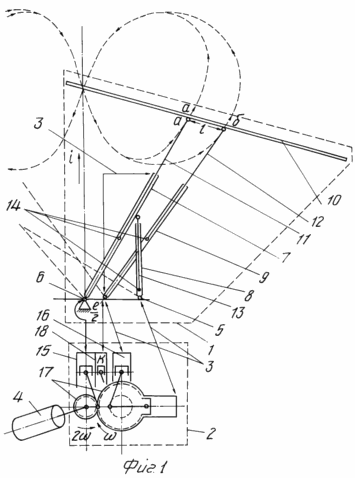
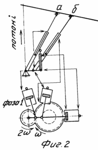
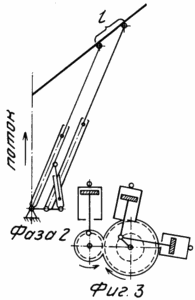
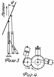
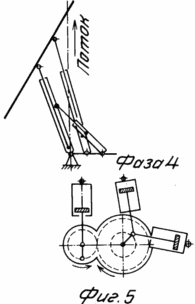
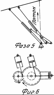
BRIEF DESCRIPTION OF THE DRAWINGS Fig. 1 shows the kinematic scheme of the power plant operation; In Fig. 2-9 shows the positions of the primary and secondary converters for two turns of the output shaft every 90 ° ; In Fig. 10 shows the variant of combining by serial connection any number of pairs of primary converters with one common secondary converter and electric generator.
 |
 |
|||
 |
 |
|||
 |
 |
|||
| ||||
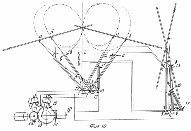 | ||||
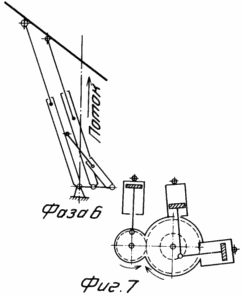
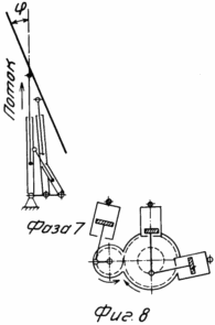
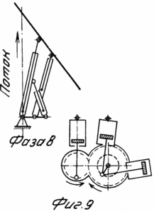
The power plant consists of at least one primary converter 1, a secondary converter 2 connecting from oil lines 3 and an electric generator 4.
The primary energy converter 1 comprises a frame 5 movably fixed to the power axis 6 on which the central hydraulic cylinder 7, the lateral hydraulic cylinder 8 and the third hydraulic cylinder 9 determining the angle of rotation of the energy receiver plane 10 are movably fixed.
The energy receiver 10 is movably attached to the rod 11 of the central hydraulic cylinder 7 and to the rod 12 of the hydraulic cylinder 9. The distance l is equal to the asymmetry value of the left and right loops of the trajectory eight, and the distance between the fixing axes of the central hydraulic cylinder 8 and the third hydraulic cylinder 9 on the frame 5 is equal to half of this asymmetry , I.e. The rod 11 of the central hydraulic cylinder 7, the rod 12 of the hydraulic cylinder 9 and the rod 13 of the lateral hydraulic cylinder 8 with opposite ends are rigidly connected to the pistons 14 made in the working chambers of the hydraulic cylinders 7, 8 and 9.
At the same time, in each hydrocylinder 7, 8 and 9, rod and rodless cavities are formed into two variable volumes. These altered volumes are connected by oil lines 3 with equivalent in size working chambers of the secondary converter 2 without any locking or regulating bodies.
The secondary transducer 2 is two piston oil pumps 15 and 16 combined by non-slip transmission so that the rotational speed of the crankshaft of the oil pump 15 operating on the central hydraulic cylinder 7 is twice the rotational speed of the crankshaft of the pump 16 operating on the side hydrocylinder 8 and rotary Hydraulic cylinder 9. This is achieved, for example, by connecting their shafts with two gears 17 having a gear ratio of 1: 2.
In principle, the oil pump 15 may have one cylinder, and the oil pump 16 has two cylinders arranged in a straight line (for a 90 ° shift in phase) to each other and communicating with the hydraulic cylinders 7, 8 and 9 with oil lines 3 as shown in FIG. 2. However, in order for the serial communication of the rod cavity of the central hydraulic cylinder 7 to the rodless cavity of the rotary hydraulic cylinder 9 to provide an equivalent in action to the hydraulic cylinders 7 and 9, it is necessary or to reduce the diameter of the hydraulic cylinder 9, as shown in FIG. 2, or compensation of the volume occupied by the rod 11, the additional cylinder 18 in the pump 15 with the same diameter of all the hydraulic cylinders, as shown in FIG.
The action of the main and compensating cylinders of oil pumps 15 and 16 should be simultaneous, which is achieved, for example, by placing their connecting rods on one crank.
An energy installation with one primary converter 1 is operable only if there is a weather vane or other device forcing the energy receiver 10 to flow, which is a significant drawback.
To eliminate it, two primary transducers 1 are disposed in the frame 5 in pairs. In this case, their energy receivers 10 along the height of the power axis 6 are displaced by at least a width and are arranged opposite each other with respect to the direction of flow, as shown in FIG. 3.
If it is necessary to obtain a significant unit power of the installation on the secondary converter 2, any number of primary converters 1, as shown in FIG. 2, can be closed by sequentially communicating their measured volumes. 3.
Parallel communication of rod and rodless chambers of primary and secondary converters is possible, but in this case the number of cylinders of the secondary converter must correspond to the total number of hydraulic cylinders of primary converters.
The communication by the oil lines of 3 variable volumes of the hydraulic cylinders of the primary converters with the equivalent volumes of the working chambers of the secondary converter 2 and the filling of these volumes, for example with oil, due to the practical incompressibility of the fluid, enclose all the movable elements of the described construction in a rigid kinematic connection in which each angular position of the shaft of the electric generator 4 and the crankshafts Oil pumps 15 and 16 corresponds to the unique spatial position of the pistons of the hydraulic cylinders 7, 8 and 9, and hence the points of movable fixation of the energy receivers 10 on the rods 11 and 12 of the hydraulic cylinders 7 and 9 (points a and b).
That is, a hydraulic rigid kinematic coupling is used here, in which the trajectory of the energy receivers is composed of the longitudinal-transverse displacement of the rods of the hydraulic cylinders 7, 8 and 9.
The rigid kinematic connection of the elements of the power plant determines the interdependence of their spatial position and causes the rotation of the payload shaft when moving the energy receivers 10 under the pressure of the wind or the water flow and vice versa: the rotation of the shafts of oil pumps 15 and 16 causes the energy receivers 10 to move according to the most optimal law similar to The law of motion of the working bodies of the prototype, when the point of attachment of the receiver 10 to the rod 11 makes an eight-shaped trajectory, and the energy receiver 10 itself, having accomplished the useful work of the movement of the direct flow by the working plane from one side of the flow, under the action of the flow and useful work of already others, Of the primary converters 1 and continued rotation of the shaft of the secondary converter 2, returns to the starting position for the subsequent swing on the other side of the flow direction with the end edge at an angle close to zero, which achieves a significant reduction in the aerodynamic (hydrodynamic) resistance to its displacement and high efficiency of the power plant.
The above refers to the n-th number of pairs kinematically connected to each other through the secondary converter 2 of energy receivers 10.
It should be noted that, since the rotation of the energy receiver 10 occurs organically under the pressure of the flow, simultaneously with the reciprocating movement of the fixing points on the rods 11 and 12, i. With the creation of a torque varying from the maximum to zero on the payload shaft, it is possible to operate the power plant with one pair of oppositely located energy receivers 10, if conditions for their transition through the position (phase) 3 are created by inertia, Theoretically, to return the energy receiver 10 back to the initial position of energy costs is not required.
Thus, two or more pairs of primary converters must be included in the kinematic connection to equalize the resultant moment on the payload shaft, reliably passing energy receivers 10 through the point of unstable equilibrium of the arms and creating a significant unit capacity of the power plant.
The expected efficiency of the proposed power plant, if the internal mechanical and hydraulic losses in the gears are neglected, will depend on the resistance to movement of the working elements in the flow.
In order to reduce the resistance to the movement of energy receivers 10 back to their original position opposite to the flow, the plane of energy receivers 10 is rotated by the rod 12 of the hydraulic cylinder 9 so that its action is ensured by movement not by the plane but by the end edge.
Consequently, the efficiency of an ideal power installation with an energy receiver 10 moving against the flow with a strictly end edge (at zero plane angle to the direction of flow) will be unity, since, as already noted, the turn of the energy receiver plane 10 itself occurs under the action of a flow with the creation of a useful moment , Transmitted to the shaft of the secondary converter, as can be seen from the kinematic diagram of FIG. 2, and the reverse energy consumption is eliminated in any position of the energy receiver 10.
Theoretical efficiency of an idealized (without internal losses) power plant h can be estimated by the formula ![]()
Flow to the plane of the energy receiver.
In general, the efficiency of the plant can be expressed by the relation ![]()
Where k is the design coefficient characterizing the minimum aerodynamic resistance of the energy receiver when it flows around the stream at j = 0;
H fur factor that characterizes internal mechanical losses;
H Hydr is a coefficient characterizing internal hydraulic losses.
Thus, at angles of rotation of the energy receiver plane to the direction of flow from 0 to 30 o, the efficiency of the proposed installation is always greater than the efficiency of known wind turbines and hydroturbines, because Lies in the range h = 1 to 0.5.
The advantages of the proposed power plant include the possibility of obtaining aggregates of any unit capacity due to the removal of the design and technological barrier inherent in the well-known wind turbines; More complete use of wind energy and water flow; A small dependence of the rotational speed of the payload shaft, and with the use of a generator on a. from. Application No. 4246840 complete independence of wind speed; The effect of environmental restrictions; Lower requirements for manufacturing technology.
CLAIM
The power installation is predominantly for the use of wind energy, flat rivers and tidal currents, containing energy receivers that are self-orienting on the moving stream, converters and a power generator connected to them by means of a transmission, characterized by the fact that it is made in the form of a hydraulic system, Including three hydraulic cylinders of the primary converter for each energy receiver, three main and three additional cylinders of the common secondary converter, the cavities of which are respectively interconnected by oil lines, wherein in the primary converter the central hydraulic cylinder is movably attached to the frame, which is pivotable about the power axis, connected to The rod of the lateral hydraulic cylinder acting on the central as a rocking link, its rod is movably connected to a rectangular energy receiver whose angle of rotation relative to the rod and the direction of flow changes under the action of the rod of the third hydraulic cylinder and movably attached to the common frame, and A secondary transducer whose crankshaft is connected to an electric generator are two reciprocating oil pumps with a ratio of 1: 2, with two parallel cylinders and a third cylinder perpendicular to them, the cavities of which are communicated with the cavities of the lateral hydraulic cylinder of the primary transducer, the length of the energy receiver being selected The commensurate magnitude of its translational motion is perpendicular to the direction of the moving flow, all energy receivers are pairwise, firstly, uniformly shifted in the phase of motion and, secondly, are symmetrically and opposite to the direction of the moving flow.
print version
Date of publication 02.04.2007gg
![]()

Comments
Commenting on, remember that the content and tone of your message can hurt the feelings of real people, show respect and tolerance to your interlocutors even if you do not share their opinion, your behavior in the conditions of freedom of expression and anonymity provided by the Internet, changes Not only virtual, but also the real world. All comments are hidden from the index, spam is controlled.