
|
Start of section
Production, amateur Radio amateurs Aircraft model, rocket-model Useful, entertaining |
Stealth Master
Electronics Physics Technologies Inventions |
Secrets of the cosmos
Secrets of the Earth Secrets of the Ocean Tricks Map of section |
  |
| Use of the site materials is allowed subject to the link (for websites - hyperlinks) | |||
Navigation: => |
Home / Patent catalog / Catalog section / Back / |
|
INVENTION
Patent of the Russian Federation RU2075639
![]()
WIND POWER PLANT
The name of the inventor: Zabegaev AI; Gorbunov Yu.N .; Naumov VV; Kutuzov VV; Smirnov S.L .; Novak Yu.I .; Demkin V.V.
The name of the patent owner: Limited Liability Partnership Firm "Obshchemash-engineering"; Research and Production Association "Vetroen"
Address for correspondence:
Date of commencement of the patent: 1995.04.20
Utilization: The invention relates to wind power and can be used in wind power plants for power generation using synchronous generators for this purpose. SUMMARY OF THE INVENTION: The wind power plant comprises a tower, a wind wheel, a multi-stage multiplier, a flywheel, a coupling, a generator, a control system. It is equipped with a clutch device containing a disconnected clutch, a brake, an additional shaft, the large pinion gear of the intermediate shaft being connected to two output high-speed shafts, the main and additional ones, one of which is hollow and connected to the clutch release clutch, the central output element which, via an additional shaft , Passed inside the hollow output shaft of the multiplier, is connected to the flywheel located on the other side of the multiplier relative to the disconnected clutch, and the other additional high-speed shaft is connected to the controlled brake. Additionally, in the wind power plant, the brake and the clutch device are mounted on the multiplier housing on the side opposite to the generator and the wind wheel, while the brake can be made mechanical, shoe type or disk, and electromagnetic. The switchable clutch of the wind power plant is made friction, single or multi-disc, and comprises an axial force adjusting unit for pressing the discs, the clutch pressure element being directly connected to the drive mechanism. The clutch shutdown drive in the basic version is made in the form of a series-connected electric motor, reducer and a screw-nut pair in which the screw is connected to the output shaft of the reducer, and the nut is pivotally connected to the pressing element of the disengaged clutch, and in a further embodiment in the form Single unit and is hingedly fixed to the coupling body, and the pressing member is in the form of a first-kind lever hinged to the coupling pusher.
DESCRIPTION OF THE INVENTION
(EN) The invention relates to wind power, specifically to wind power plants (VEU) with synchronous generators mainly operating on a network.
A wind power plant is known, see description for as. USSR No. 1703854 dated 25.12.89, cl. F 03 D 7/02, [1] comprising a tower, a wind wheel with a horizontal axis of rotation that is connected through a horizontal shaft to a generator located inside the head mounted on the head to rotate about a vertical Axis.
This known device has a simplified transmission scheme and does not ensure the constant speed of rotation of the rotor shaft, since it does not contain devices for the power decoupling of the shaft of the wind wheel from the generator shaft, which predetermines the development of oscillatory processes for the "generator-wind wheel" system with changes in the wind speed.
In addition, it does not contain braking devices, which reduces the safety of the work of the windmill and potentially leads to an emergency situation.
The wind power plant is known (see book by EM Fateev "Wind turbines", Gosenergoizdat, Moscow Leningrad, 1945 wind wheel with a horizontal axis of rotation, the horizontal shaft of the wind wheel is connected with a multiplier connected to the generator via a hydraulic coupling.
Such a technical solution has the following disadvantages:
- Mechanical braking of wind turbines is ensured, which leads to low safety of operation of wind turbines;
- The wind turbine has large dimensions of both the installation itself and the gondola;
- A large mass of wind turbines, including a large specific gravity;
- Insufficient reliability, primarily due to the presence of a hydraulic coupling;
- Limited resource of work;
- The increased cost of both the installation itself and the electricity it generates;
- The limitation of the universality of adaptability to the conditions of wind flows.
The wind power plant described in AS is known. The USSR N 1325189 from 01/07/186. Cl. F 03 D 7/04, [3] containing a wind wheel with moving blades, a two-stage multiplier with an intermediate shaft, a coupling, a generator, a control system.
According to the function performed, the design features and the result achieved, such a known technical solution is closest to the claimed one and is therefore chosen as a prototype.
This known solution has the following drawbacks:
- The power flow of the wind turbine "two-stage multiplier - electric generator" is permanently closed, which predetermines the development of oscillatory and self-oscillatory processes in the power stream, as a result of which intense loads can arise, leading to the destruction of the windmill or emergency situation;
- Limited resource of the windmill due to increased loads that arise in the transmission when the wind power is affected by the vibrational power from the wind flow;
- The power flow of the wind turbine is oriented only in one direction, it predetermines the increased dimensions of the gondola of the windmill and, correspondingly, its weight and cost;
- The wind turbine does not have mechanical braking devices, which determines the low reliability and safety of operation of the wind turbine and does not meet the requirements of modern safety standards.
These disadvantages of this well-known device are for the most part principal for wind power classes in the tens and the first hundreds of kW, and designed to work both with the network and with the autonomous consumer does not allow to essentially create a modern practically efficient wind turbine.
The task set before the developers of this windmill is interrelated for a number of factors and conditions.
The goal is not achieved by the sum of known results, a complex solution having an inventive level is required.
The object of the invention is:
- Ensuring trouble-free operation of the wind turbine due to the possibility of erosion of the power flow in the event of power fluctuations in the transmission;
- Increase of reliability and safety of operation of the VEK due to the use of remotely activated braking devices;
- Reducing the size of the gondola and reducing the material consumption of the windmill by using a tight arrangement of transmission and electric power equipment in the gondola of the wind turbine;
- Reduction of the loads acting on the units and aggregates of the transmission of the windmill and the power structure and increase in the resource of the windmill.
The goal is achieved due to the fact that the wind power plant is equipped with a brake, a flywheel, a disengaged clutch, the input and output elements of which are withdrawn from the same side of the clutch, the input element made in the form of a hollow shaft is installed coaxially with the output element, the intermediate shaft of the multiplier Is connected to two output high-speed shafts, one of which is connected to the controlled brake and the other is hollow and is connected to the hollow input element of the disengageable clutch whose central output element is coaxially passed inside the hollow high-speed shaft of the multiplexer and is connected to a flywheel connected in series with the generator .
An additional difference of the claimed device is that the brake and the clutch device are mounted on the body of the multiplier on the side opposite to the generator, and they can be mounted both from the side of the wind wheel and from the opposite one.
The brake can be made mechanical, shoe or disk type or electromagnetic.
The clutch shutdown drive is made in the form of a series-connected electric motor, reducer and a "screw nut" pair, in which the screw is connected to the output shaft of the reducer, and the nut is pivotally connected to the clutch release clutch element. It can be made in the form of a single unit and pivotally fixed to the housing of the coupling, and the pressing element is in the form of a first-kind lever hinged to the coupling pusher.
The switchable clutch is made frictional, multi-disk, with the possibility of adjusting the axial force of the preload of the disks. The clutch pressure element can be directly connected to the clutch drive mechanism in the clutchless clutch release actuator.
The attached drawings are depicted.
 |
 |
 |
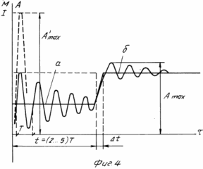 |
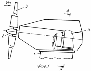
FIG. 1 wind power plant. Side view. Gondola, wind wheel.
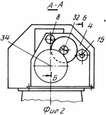
FIG. 2 wind power plant. Section AA, see FIG. 1
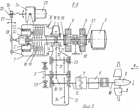
FIG. 3 wind power plant. Structural-layout scheme of power flow of wind turbines.
FIG. 4 oscillations of the blades with a sudden application of the braking torque to the transmission to the intermediate shaft of the multiplier and with the change of the moment of inertia of the rotating parts of the transmission:
"A" the effect on the combined transmission of the braking torque is a stepwise (abruptly) applied angular acceleration
"B" the change in the angular acceleration when the transmission is disconnected when the coupling is switched off.
The figures and the text indicate: 1 tower of the windmill, 2 wind wheels, 3 - blades of the wind wheel, 4 multistage (two or more) multiplier, 5 - generator, 6 control system for the blades of the wind wheel, 7 - clutch, 8 brake, 9 Flywheel, 10 hollow shaft, 11 gear clutch, 12 multiplier input shaft 4, 13 multiplier power housing 4, 14 clutch input element 7 step drive cage, 15 central clutch output element 7, 16 hollow output high-speed multiplier shaft, 17 output high-speed stage Multiplier, 18 driven clutch friction disk 7, 19 clutch leading clutch disc 7, 20 clutch inner clutch 7 - non-rotating part, 21 clutch inner clutch 7 rotating part, 22 spring, 23 clutch shut-off motor 7, 24 clutch shut-off clutch reducer 7, 25 screw, 26 nut, 27 lever, 28 pusher, 29 brake pads, 30 additional high-speed shaft of the multiplier, 31 big multiplier intermediate shaft, 32 multiplier intermediate shaft, 33 small idler shaft of the multiplier, 33 big gear of the input (slow-moving) Multiplier shaft, 35 small gear of additional high-speed shaft 30, 36,37 couplings, 38 central flywheel bearing assembly 9.
The sign "X" indicates a fixed (for example, splined) connection with the possibility of transferring the torque.
"B" flange, made on the power housing 13 of the multiplexer, for securing the disconnected coupling 7.
The wind power plant comprises a tower 1, (see Figures 1, 2) with a gondola with a rotor blade 2 with rotary blades 3, a multi-stage multiplier 4, a generator 5, a control system 6 on the position of the blades 3, which disengages the clutches 7 , A controlled brake 8, a flywheel 9. The wind wheel 2 is mounted in a nacelle on a hollow shaft 10 connected by a connecting jaw clutch 11 to the input slow-speed shaft 12, a multi-stage multiplier 4 having a power housing 13. In the disengaged clutch 7, the outlet 14 and the inlet 15, , The torque transmitting elements are withdrawn from the same side of the sleeve 7, the input element 15 made in the form of a hollow stepped driving cradle is installed coaxially with the output element 14 of the clutch 7 and is connected to the output stage 17 of the multiplier 4. The central output element 14 clutch shaft 7 is passed through the hollow high-speed shaft 16 of the multiplier 4 and is connected to the flywheel 9 connected in series with the generator 5. The disengaged clutch 7 with its housing is fixed to the power housing 13 of the multiplier.
The torque transmitted by the clutch 7 is controlled by adjusting the value of the axial force of the clamping of the friction plates 18 and 19 by means of a pressing member consisting of an external non-rotating 20 and an internal rotating part 21 compressed by a spring 22. 0 Switching off of the clutch 7 is effected by a drive comprising An electric motor 23, a reducer 24, a screw 25, a nut 26, a lever 27 connected to it at one end and hinged to the other end of the coupling by the other end, the third point of the lever 27 is pivotally connected via a pushrod 28 to the clutch pushing member 20.
The clutch shutdown drive can be implemented as a single unit including the motor 23 and the reduction gear 24 and pivotally mounted on the coupling body, and the pressing member is in the form of a first-kind arm pivotally connected to the pusher 28 of the clutch 7.
The controllable brake 8 is mounted on the housing 13 of the multiplier 4 on the side opposite to the generator 5 and the wind wheel 2, as is the switchable clutch 7 with the drive. The brake 8 is made of a mechanical, for example, shoe type, containing a brake drum and pads 29, or disc. It is possible to implement an electromagnetic brake, for example hysteresis (as a mechanical brake, for example, a standard shoe brake type TKP [4]) can be used.
The brake 8 is connected to the additional high-speed shaft 30 of the multiplier 4 and through the large gear 31 of the intermediate shaft 32, the small intermediate shaft gear 33 with the large gear 34 of the input slow-speed shaft 12 of the multiplier.
The wind power plant works as follows
Let us consider the general case of work.
Rotation of the shaft 10 of the wind wheel 2 through the gear clutch 11 drives the input shaft 12 of the multiplier 4. The brake shoes 29 in the brake 8 are pressed. The hollow output shaft 16 of the multiplier 4, connected via a splined connection (indicated by "x" in Figure 3), with the stepped driving cradle 15 - the input element of the disconnected clutch 7, transfers rotation to the leading friction discs 18 of the clutch 7, to the driven discs 19 and rotates The central output element 14 is the shaft of the sleeve 7 which, through the coupling 36, for example, rotates the handwheel 9 and then rotates the power generator 5 through the coupling sleeve 37.
When the speed of wind flow v Ґ and, respectively, the power supplied to the shaft 10 by the wind control system is controlled by the control system 11, the position of the blades of the wind wheel controls the power input to the multiplier, thereby achieving the stable operation of the wind turbine.
Due to errors in the control and delay system, and because of the presence in the force stream of the "wind-wheel-transmission-generator" of elastic-mass elements, the vibrational power input to the multiplier input can lead to the development of oscillatory processes in the transmission. (The term "transmission means a combination of power elements involved in transferring loads from the wind wheel to the generator, including the wind wheel shaft, multiplier, clutch, flywheel, couplings, braking device, etc.).
As the intensity of the oscillations increases, the leading 18 friction discs slip in relation to the driven discs 19 in the sleeve 7, thereby limiting the power fluctuations controlled by the magnitude of the spring force of the spring 22, as well as the rapid decay of the subsequently dissipative dry friction coupling in the coupling 7.
With the correct selection of the stiffness and inertia characteristics of the transmission elements in the mathematical modeling of the operation of the wind turbine, the considered construction of the transmission makes it possible to almost completely eliminate self-oscillating phenomena in the operation of wind turbines under conditions of variable wind speed, including underload conditions of the generator, overloads, including short-circuit generator and sudden Unauthorized) operation of the brake and a number of other situations.
The flywheel 9, with limited vibrations due to its inertia, practically quenches the oscillations and does not allow them to pass to the generator 5, ensuring its stable operation. The latter circumstance is very important, since the synchronous generator is fundamentally an unstable electric machine and is prone to "self-rocking". The moment of inertia of the flywheel 9 is chosen by calculation in the simulation of the dynamic system "wind-wheel-transmission-generator", proceeding from the achieved effect on the uniformity of the system operation and structural limitations on mass and layout. So, for the power of the unit 300 kW with the tightening torque of the clutch 7 at 1, 3 of the nominal value of the torque transmitted by the transmission at nominal power, the flywheel has the following parameters: I 30 kg h second 2 m, diameter 0.85 m, weight 1200 kg.
In the mode of braking the wind wheel and stopping the wind turbine its operation is as follows.
The technology of braking and stopping of the wind turbine considered below is considered in detail in another application of the same applicant, N 31/4 95 from 10.04.95 in VNIIGPE: "Method of wind power plant management", which is an independent technical solution.
At the command of the control system of the windmill (not shown in the drawings), the blades 3 of the wind wheel 2, with the help of the blade position control system 11, translate into the vane position. Wind-wheel 2 at the same time loses power. At the same time, the generator 5 is taken out of the electrical network. After the generator 5 is withdrawn from the network, the pads 29 in the controllable brake 8 cease to be held in the retracted position from the drum, thereby applying a braking torque to the transmission, and particularly first to the additional high-speed shaft 30 and, respectively, to the intermediate shaft 32 of the multiplier.
The brake power, more precisely, the magnitude of the braking torque is set close to or equal to the value of the nominal torque transmitted by the transmission when the windmill is operating at rated power.
When the brake 8 is activated, the rotating elements of the transmission and the wind wheel receive a dynamic loading pulse due to an almost sudden application of the braking torque. The magnitude of the angular acceleration of deceleration is determined from equation ![]()
Where M is the magnitude of the braking torque,
I is the total moment of inertia of the rotating parts of the transmission and the wind wheel.
The blades of the wind wheel with a sudden application of the braking torque bend and make damped oscillations. This mode of loading for the blades is very unfavorable: there are significant loads, which significantly reduces the service life of the wind wheel. Therefore, in the practice of designing a wind turbine limit the number of such loads, for example to 20.50 for the entire period of operation of 15.20 years.
The introduction of the flywheel into the rotating mass system, as studies show, leads to an increase in the reduced moment of inertia of the rotating parts of the "wind-wheel-transmission-generator" system by a factor of 2.3 (with a smaller increase, the introduction of the flywheel can be ineffective, and the need to "adjust" the moment of inertia is caused by different angular Speed of different transmission elements). According to equation (1), at the same value of the braking moment M, it is possible to reduce the magnitude of the angular acceleration of inhibition and by 2.3 times. As a result, the loads arising in the blades of the wind wheel during the oscillations are substantially reduced, as a result of which there is no reduction in the life, as is the case with the known designs of the wind turbine.
After the expiration of the time interval for which the oscillations of the blades resulting from the application of the braking torque are damped (in engineering practice it is permissible to use the decrease of the oscillation amplitudes from the initial to the level of 10.15% of the initial 100% in the quality of the decay of the process), further operations are possible With the technology of braking the windmill. For glass and carbon fiber structures of windmill blades, the time interval required to achieve the indicated oscillation amplitudes during attenuation is 2.5 cycles of T oscillations.
Thus, after a time t (2.5) T, where T is the period of the lowest frequency of the transverse oscillations of the blade in the vane position, has a minimum stiffness in the direction of rotation), the clutch 7 is switched off and at least the separation of the rotating transmission elements is reduced (in the considered version of the wind turbine design) to two parts:
Part 1: the wind-wheel brake multiplier;
Part 2: flywheel generator,
Which leads to an abrupt increase in the angular acceleration of the braking, see Fig. 4.
To this end, the motor 23, through the reduction gear 24, rotates the screw 25 and moves the nut 26 and rotates the lever 27, thereby pushing the spring 22 and releasing the friction plates 18 and 19 further with the pusher 28 and the pressing member 27. The clutch 7 is not switched off suddenly, Some time necessary to free up the discs, for example, for 3 seconds. If the magnitude of the applied braking torque is constant, this increases the angular acceleration of the braking Yў according to equation (1) by decreasing the moment of inertia of the rotating parts due to the switching off of the flywheel and the generator. It is important to note that the increase in Yў is not done suddenly, as a result of which the resulting oscillations of the blades have a much lower intensity than at the first application have a much lower intensity than when the first application of the braking moment. This ensures a quick and effective braking of the wind wheel, its stopping and holding in the inhibited position.
The flywheel and generator in this case make a free run. In Fig. 4 shows the vibration pattern of the wind wheel blades under braking, which is realized during the operation of the claimed wind power plant, illustrating the efficiency of the claimed wind turbine in this mode.
With the braking technology considered, the heat release in the gondola of the wind turbine is significantly reduced, since the braking of the combined transmission with an increased moment of inertia takes about 2.5 periods of the natural oscillations of the blade, for example, at a frequency of 0.8.1.5 Hz and, respectively, periods of 1.2.0.67 seconds. This interval is 2.5.8.0 seconds. After disconnecting the transmission, the wind wheel at the indicated value of the braking torque is decelerated in 10.20 seconds.
For example, when an accident occurs in a wind turbine, the connection to the grid is lost and it turns out to be de-energized, it is likely in the event of a generator or power-handling device failure and communication with the network, the brake 8 ceases to hold the pads 29 in the diluted state. The braking torque is applied to the transmission, and due to an autonomous power source (not shown in the drawings), the blades are moved to the vane position, the transmission opens and the wind wheel stops, which remains in a retarded condition after the stop. This provides increased safety of wind turbines.
The claimed wind turbine has a tight arrangement of power equipment in the gondola, which determines its small size and volume.
The wind turbine allows to place the power, electrical and even electronic control system compactly in the gondola, due to which convenient maintenance is achieved, the dimensions of the gondola are reduced and the repair work is facilitated.
Thus, the sleeve 7 is formed in such a way that the entrance to it and the outlet are made on one side on the side of the flange joint "B" of the multiplier, see Fig. 3. The flywheel 9 is made from two half-couplings of semi-flywheels with a central bearing assembly 38, which determined its high compactness in the axial direction.
The installation of the brake 8, the clutch 7 on the body 13 of the multiplier allows them to be assembled in a single power unit with high local and general stiffness, and to save weight and dimensions of the power frame on which the multiplier, generator and shaft of the wind wheel are mounted.
The brake 8 is driven by an additional high-speed shaft 30, a multiplier connected to its intermediate shaft 32, which, on the one hand, facilitates the selection of the brake by the amount of the braking torque by assigning a corresponding gear ratio of this additional step-up step, allowing the use of brakes with reduced torque values, And on the other hand it creates an independent brake flow that, when a high-speed stage of the multiplier, a coupling 7, a flywheel 9, couplings 37 and 38, or a generator 5 breaks, ensures braking of the wind turbine, which increases the reliability and safety of operation of the wind turbine.
In addition, the required life time of the mechanical brake 8 is 0.5.1.0 of the operating time of the windmill, which imposes lower requirements on the endurance of the brake flow units, reducing the dimensions and facilitating the construction (here we note, for example, that the classical performance of an industrial multiplier and special performance For a VIZ with a resource of 15 years before overhaul with variable loads with a high modulation amplitude leads to an increase in the dimensions of the multiplier by 2 times in basic dimensions and 4.5 times the mass.)
The rotation of the power flow from the wind wheel to the multiplier and from it through the disconnected clutch 7 again to the wind wheel, see Fig. 3, provides a high density of layout. The coupling 7 and the flywheel 9 with the generator 5 can be disposed with a mirror image with respect to the indications in FIG. 3 layouts. The flange "B" will be located on the multiplier body 13 on the side of the wind wheel. This solution is identical to the one described above, and is considered as additional. In a number of cases, it may be preferable, and therefore rendered in additional claims (paragraphs 2 and 3).
The clutch release actuator 7 as a basic embodiment is considered a lever type, for example with a first-type lever with an electric motor 23 combined in a single structural unit with a gearbox 24 pivotally attached to the housing of the sleeve 7. It is possible to drive the actuator, by a spindly direct engagement of the screw 25 with a non- 21 of the clutch member 7. These embodiments are additional and included in additional clauses (clauses 9, 13) of the claims.
The variant of the multi-plate clutch, with a steel disc 18, 19, operating in an oil bath, is considered as the main variant of the implementation of the disconnected coupling 7. For this variant, a practical design of a 300 kW wind turbine has been developed. [6] At the same time, it is possible to use single- and double-disk dry clutches with the use of friction materials, including cermets with a high friction coefficient. Generally, in the claimed device, the clutch need not be frictional, it can be electromagnetic, but contain the necessary features of claim 1, which determine the basic set of essential characteristics necessary for the operation of the wind turbine, provided that the goal is achieved. Therefore, the embodiments of the friction clutch, the multi-disc clutch, the adjustable clamping force of the discs and the magnitude of the transmitted torque, are included in the additional claims.
The claimed device is oriented primarily for use in an industrial network with a synchronous generator, they are progressive, and its use allows achieving the stated objective of the invention:
- To ensure trouble-free operation of the wind turbine due to the possibility of opening the power flow in the event of a power fluctuation in the transmission;
- Increase the reliability and safety of the operation of the wind turbine by using remotely activated braking devices in it;
- To reduce the dimensions of the gondola and reduce the material consumption of the windmill by using a tight arrangement of transmission and electric power equipment in the gondola of the windmill, to increase the convenience of maintenance;
- To reduce the loads acting on the units and aggregates of the transmission of the windmill and the power structure and to increase the resource of the windmills.
CLAIM
1. A wind power plant comprising a tower, a wind rotor with rotary blades, a multistage multiplier with intermediate shafts, a clutch, a generator, a control system characterized in that it is provided with a brake, a flywheel, a disengaged clutch, the input and output elements of which are withdrawn from one and the same And the input element, made in the form of a hollow shaft, is installed coaxially with the output element, the intermediate shaft of the multiplier is connected to two output high-speed shafts, one of which is connected to the controlled brake and the other is hollow and connected to the hollow input element of the disengaged clutch , The central output element of which is coaxially passed inside the hollow high-speed shaft of the multiplier and is connected to a flywheel connected in series with the generator.
2. Installation according to claim 1, characterized in that the brake and the clutch device are mounted on the multiplier body from the side opposite to the generator.
3. Installation according to claims 1 and 2, characterized in that the brake and the clutch device are mounted on the body of the multiplier on the side opposite to the wind wheel.
4. Installation according to claim 1, characterized in that the brake is made mechanically.
5. The plant according to claims 1 and 4, characterized in that the brake is of a shoe type.
6. The plant according to claims 1 and 4, characterized in that the brake is of disk type.
7. An installation according to claim 1, characterized in that the brake is made electromagnetic.
8. A plant according to claim 1, characterized in that the clutch shut-off drive is made in the form of a series-connected motor, gearbox and a pair of screw nut, in which the screw is connected to the output shaft of the reducer, and the nut is articulated to the pushing elements of the disengaged clutch.
9. An installation according to claims 1 and 8, characterized in that the clutch shut-off actuator is made in the form of a single unit and pivotally mounted on the clutch body, and the pressing member is in the form of a first-kind arm pivotally connected to the clutch pusher.
10. An installation according to claim 1, characterized in that the disengaged clutch is frictionally clogged.
11. An installation according to claims 1 and 8, characterized in that the disengaged coupling is made of a multi-disc.
12. Apparatus according to claims 1, 8 and 9, characterized in that the switchable clutch is configured to adjust the axial force of the preload of the discs.
13. Apparatus according to claims 1, 8 and 9, characterized in that the clutch pressure element is directly connected to the clutch drive mechanism.
print version
Date of publication 02.04.2007gg
![]()


Comments
When commenting on, remember that the content and tone of your message can hurt the feelings of real people, show respect and tolerance to your interlocutors even if you do not share their opinion, your behavior in the conditions of freedom of expression and anonymity provided by the Internet, changes Not only virtual, but also the real world. All comments are hidden from the index, spam is controlled.