| section Home
Production, Amateur Radio amateur Model aircraft, rocket- Useful, entertaining |
Stealth master
Electronics Physics Technologies invention |
space Mystery
Earth Mysteries Secrets of the Ocean Stealth section Map |
  |
| Use of material is permitted for reference (for websites - hyperlinks) | |||
Navigation: => |
Home / Products Patents / In the section of the catalog / back / |
|
INVENTION
Russian Federation Patent RU2075640
![]()
CONTROL METHOD Wind Turbine
Name of the inventor: Zabegaev AI .; Gorbunov YN .; Kleshenko VG .; Novak YI .; VV Dyomkin
The name of the patentee: Limited Liability Company "Obschemash- Engineering"
Address for correspondence:
Starting date of the patent: 1995.04.20
Usage: The invention relates to wind energy, specifically for the wind power plant (wind turbines), electric power is generated using synchronous generators running on a network. The inventive method for controlling a wind power installation includes installation of power generation when the generator is on a network, the aerodynamic limit the power developed by the wind wheel and propeller stop. The mode of operation of the generator to the network at fault blade rotation system of rotating elements of the installation applied brake torque, the magnitude of the corresponding nominal torque in the transmission, then output the generator from the network and provide additional braking, turning a generator to additional hysteresis brake mode setting when the hysteresis braking point in size, does not exceed the rated torque of the transmission, and the time t of additional braking torque application on the one hand selected from t i of (2 ... 5) t, where the t - the period of the lowest frequency of oscillation of the blade propeller, and on the other - on the offensive conditions w max = w 2 nom, where w max - the maximum permissible speed of the wind wheel, w nom - nominal speed propeller. Additionally, inhibition of rotating elements of the installation process monotonically decrease the torque M m1, developed by an electromagnetic brake, to reduce the angle of rotation w propeller speeds of up to 0.3. . . 0.5 nominal speed of rotation w nom cut off electromagnetic brake at the same time as the electromagnetic brake is used in the generator mode, the hysteresis brake.
DESCRIPTION OF THE INVENTION
The invention relates to wind energy, specifically for the wind power plant (wind turbines), electric power is generated using synchronous generators running on a network.
The research work of high power wind turbines, for example 250 kW, have shown that when the wind turbine in high winds in excess of 13.15 m / s can occur during emergencies samorazgone propeller.
Wind turbine control system is tuned to the excess over the nominal angular velocity, for example at 4.5% At w = (1,04 ... 1,05) w for wind turbine control systems team made translation propeller blades in the feathered position.
However, in some cases, for example when the fault mechanism of rotation of the blades, hydraulic system failure, damage to rods and other faults, but also with a lack of driving power, for example, at low temperatures and the increased friction, possible absenteeism propeller blades in the feathered position.
As a result, wind wheel, continuing to select power from vetropotokah begins to self-accelerate. When the propeller angular velocity exceeds 4.5% of the nominal disrupted synchronous generator to the network, whereby the generator may overload burn. Windwheel PTO loss from it continues acceleration, the rotation speed can be up to 2, 3 or more times the nominal rate. Power drawn from the vetropotokah, growing and emergency is imminent.
Review "scenario" in 1993 there were a number of accidents of wind turbines 250 kW Ukraine, accompanied by destruction of the propeller. In Russia and in an emergency situation.
The research work of the wind turbine in potentially emergencies showed that the problem of an emergency stop the wind turbine control system in case of failure of the blades position is essential and can not be solved simply by setting the braking device. So, when w = 2 w rated power to the propeller is in 2 or more times greater than the nominal. Installation of the mechanical brake to stop the propeller, with a capacity of at least greater than the specified power developed by the wind wheel, on the one hand leads to a highly dynamic loading of the blades of the wind wheel, on the other hand the necessity of recycling the heat generated by braking, for example 400,500 kW for tens of seconds, that is complex engineering problem because besides units in which heat generation occurs, disturbed temperature condition gondolas in general, which can lead to failure of the equipment from overheating.
There is a method of braking and stopping control propeller wind turbine implemented when working on the device AS USSR N 1076617, cl. F 03 D 1/00 of 28.05.82, in which the absence of wind wheel through a pneumatic brake is held in a fixed position, and when operating in braking mode, and stopping the propeller brake torque from the brake is applied directly to the propeller shaft.
The disadvantage of this known method is that the braking torque is applied directly to the propeller shaft, which requires a lot of effort into the development of the braking device, since the moment of maximum propeller is on its shaft.
In addition, the use of air brakes reduces the reliability of the wind turbine stopped, as it requires the creation of another air turbine power system in addition to the existing electrical grid, and a compressor, piping, pneumatic valves. This is a disadvantage (unless the use of wind turbines for the purposes of highly specialized compressed air).
As shown above direct mechanical braking is applied to the propeller shaft does not solve the problem definitely stop propeller at its dispersal over the rated speed, since the need of braking power can significantly exceed the nominal value of the power turbine. Therefore, solution of the problem must be sought in the direction of the aerodynamic power limitations combined with a mechanical brake.
These drawbacks limit the use of this known method and does not allow its practical use in emergency situations discussed above.
There is a method of braking and stopping control propeller wind turbine implemented when working on a device. from. USSR N 1325189, cl. F 03 D 7/04, 07.01.76, in which the power developed by the wind turbine wind wheel in routine and emergency situations, is controlled by a system of regulation blade position, which receives control signals from the sensor and the wind turbine control system.
The disadvantage of this known method is primarily that it can be implemented only if a functioning system of regulation of the blades position. Duplication device systems does not mean a clear increase reliability, as there may be cases when a working system may not have enough power to bring the blades with the PTO angles in feathered position. These cases are typical for high power wind turbines. In this case the wind wheel is accelerated to speeds increased, it rupturable power is further increased, further increasing load, respectively, leading to potential emergency.
This well-known method of controlling the brake and stop the propeller wind turbine, according to a. from. USSR N 1325189, cl. F 03 D 7/04 of 07/01/76 was the most similar to the claimed technical essence and attainable effect and is selected as a prototype, as the main direction in the fight against the class in question accident is to achieve aerodynamic power limitation, developed wind wheel, after which the task propeller stop can already be solved with the use of brakes.
This shows that only aerodynamic braking, or only mechanical braking is not sufficient for effective braking and stopping the turbine in case of emergency is not enough and a simple combination.
To resolve this problem, a comprehensive solution is not achievable simply the sum of the known results, and involve an inventive step.
Necessary to develop a new technology wind turbine emergency braking - the control method of the wind turbine that achieves conservation of strength and endurance of the wind wheel, wind turbines and transmission is eliminated emergency.
The aim of the invention is:
- improving the reliability and safety of wind turbines by preventing the development of an emergency in case of failure of the system turning propeller blades;
- improving the safety of operation of wind turbines;
- increase the resource of wind turbines by reducing the dynamic loads acting on the propeller blades, transmission, generator during braking modes, including emergency.
The goal is achieved by the fact that the operation of wind turbines in the generator mode, the network and a fault occurs, turning the rotor blade system, rotating elements installation applied brake torque, the magnitude of the corresponding nominal torque in the transmission, then output the generator from the network and create additional braking translating generator mode an additional electromagnetic brake, asking when electromagnetic braking moment, the magnitude does not exceed the rated torque of the transmission, and the time interval between the application of the first and the additional braking torque is selected on the one hand no less time damping blade vibrations caused by the first application of braking torque and, on the other hand does not exceed the dispersal of wind wheel to twice the nominal speed.
During braking, further reduce the amount of monotonous additional braking torque to achieve a wind wheel angular velocity equal to the nominal 0,3.0,5, cut off electromagnetic brake.
 |
 |
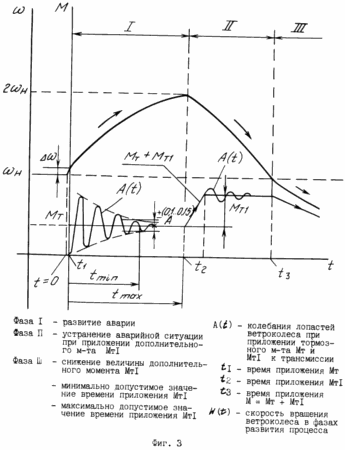 |
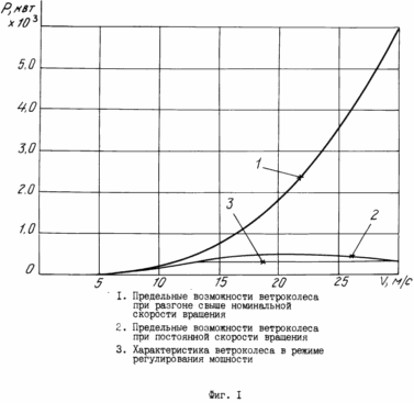
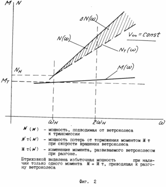
The accompanying drawings show: Fig. 1 schedule of power generated by the wind wheel on the example of wind turbines AVE-250 propeller with a diameter of 25.0 m in the mode with variable speed w (t); FIG. 2 power balance: input from the propeller to the drivetrain and braking power; FIG. 3 is a graph in steps of increasing the braking torque applied to the transmission and wind wheel and the speed w (t) propeller. Fluctuations propeller blades A (t), arising from the application to the brake transmission torque M t M T1; FIG. 4 VEU diagram illustrating an implementation of the claimed method by the example of a single-threaded performance of wind turbines with a shared transmission. |
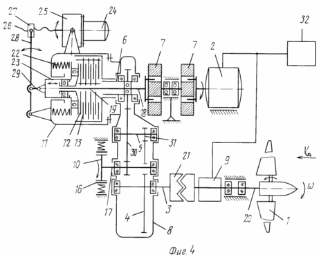
In the drawings and the text is indicated: 1 propeller blades; 2 - the generator; 3 input, low-speed shaft of the multiplier; 4 large gear multiplier; 5 intermediate shaft multiplier; 6 - output, high-speed shaft of the multiplier; 7 flywheel; 8 - multi-stage (two or more) of the multiplier; 9 position control system propeller blades; 10 controlled by the brake; 11 -vyklyuchaemaya clutch; 12 driven friction clutch plate; 13 master friction clutch plate; 14 motor off clutch actuator; 15 drive clutch gearbox off; 16 brake pads; 17 additional high-speed shaft of the multiplier; 18 output element clutches; 19 input element clutches; 20 hollow shaft propeller; 21 -zubchataya clutch; 22 Spring; 23, the pressing member; 24 motor off clutch actuator; 25 reducer; 26 screw; 27 nut; 28 lever; 29 follower; 30, the large gear of the intermediate shaft of the multiplier; 31 small gear of the intermediate shaft of the multiplier; 32 wind turbine control system; M r value of the braking torque; M n nominal value of torque transmitted in the transmission during operation of wind turbines with nominal power of Mr. N;
M n = N SG/ w SG
w Mr. rated speed propeller; w max maximum permissible speed propeller; T period of the lowest frequency of the blade propeller vibrations; Z propeller rapidity; Power factor C p.
A method for controlling a wind power installation is as follows.
When electricity generation in the mode of operation of the generator on the network perform aerodynamic limit the power developed by the wind wheel, the output of the generator from the network and stop the propeller, and the case of failure of the blades rotating system in the generator mode, the network to the rotating elements of the installation applied brake torque, the magnitude of the corresponding nominal the time of the transmission, and then output the generator from the network and provide additional braking, turning a generator mode an additional electromagnetic brake, asking if hysteresis braking point by a distance not exceeding the rated torque of the transmission, and the time t of additional braking torque application on the one hand chosen from the relation
t i (2.5) T,
where T is the period of the lowest frequency of oscillation of the blade propeller, and other conditions on the offensive
w max = w 2 nom,
where w max maximum permissible speed propeller,
w nom nominal speed propeller.
During braking, the rotating elements of the installation monotonically decrease the torque M m1, developed by an electromagnetic brake, and to achieve the angular rotation of the propeller speed w 0,3.0,5 to the rated speed of rotation w nom cut off electromagnetic brake.
Consider the implementation of the claimed method of controlling a wind turbine on the example of the wind turbine single-threaded performance, design-layout diagram is shown in FIG. 4 (detail this wind turbine is considered in the application "Wind Turbine" by the same applicant, aimed at VNIIGPE, ref. Of N 34 / 4-95 from 04.12.95 city).
Wind Turbine includes wind-wheel with rotating blades 1, a multi-stage multiplier 8, the generator 2, the position of the blades 1 9 Control system, turn off the clutch 11, controlled by the brake 10, the flywheel 7. Wind wheel installed in a gondola on the hollow shaft 20, connected through a connecting gear clutch 21 with the input low-speed shaft 3 multistage multiplier 8, having the power enclosure. The clutches clutch 11, an output 18 and input 19 elements transmitting torque, derived from the same coupler side 11, the input element 18 formed as a hollow stepped leading ferrule is mounted coaxially with the output member 19, the coupling 11 and is connected to the output multiplier stage 8. The central coupling element 18, the output shaft 11 is passed through the hollow shaft 6-speed multiplier 8 and is connected with a flywheel 7 coupled in series with the generator 2. disables its clutch housing 11 fixed to the body force multiplier 8.
The moment passed clutch 11 is controlled by adjusting the magnitude of the axial force urging the friction plates 12 and 13 via the pressure element 23, consisting of the outer non-rotating and rotating inner parts, pursed spring 22. The on-off clutch 11 is performed by the drive, including motor 24, gear 25, screw 26, nut 27, associated with one end of a lever 28 which is pivotally attached at the other end to the coupling body, the third point of the lever 28 is pivotally connected to the push rod 29, coupling 23, pressure element 11.
Controlled brake 10 is mounted on the housing by the multiplier 8, opposite the generator 2 and the wind-wheel, as well as clutches 11 with the drive. A mechanical brake 10 is made, for example shoe type comprising a brake drum 16 and shoe or disk. Possible embodiment of the electromagnetic brake, such as hysteresis (as a mechanical brake, such as a standard brake shoe type of the TAP can be used [3]).
The brake 10 is associated with an additional high-speed shaft 17 and the multiplier 8 through a large gear 30 of the intermediate shaft 5, a small gear 31, the intermediate shaft 5 with 4 large gear input speed shaft 3 multiplier 8.
The practical implementation of the method is as follows
If a fault position control system rotor blade (blade rotation) or the inability to launch the blades in feathered position due to an overload of the wind wheel (which is equivalent to a fault, because the system does not perform its function) in generator mode on the network, to the rotating elements of the transmission are applied braking torque while the generator output from the network (in the claimed decision it comes to wind turbines with synchronous generators: in the case of non-output of the generator from the network and reduce the angular velocity of the wind wheel, wind wheel generator begins to rotate, working as a motor).
The braking torque T M is applied from the mechanical brake 10 to the transmission rotating elements, for example, 5 to the intermediate shaft 6 or the output of the multiplier 8. Preferred is the application of braking torque to the intermediate shaft 6 (or shafts), as it allows more uniform load transmission and generally to increase the total value of the braking torque.
Appendix braking torque M r of the mechanical brake 10 pressure sensitive pads 16 to the brake drum is almost suddenly jump. Power brakes 10, defined as the product of the braking torque M r on the angular velocity of the wind wheel w n, and equal to the nominal power transmitted through the transmission turbine generator 2, the implementation of the braking mode is set from the value of the application conditions of the braking torque corresponding to the rated torque of the transmission during the wind turbine at rated power. In this case, the transmission overload occurs, since it is designed for continuous operation to said transmitted torque magnitude.
However, only one braking torque M m equal power at the beginning of braking power generator rated M 2 wind turbines for wind turbines stop trouble-free enough. In essence, the mechanical brake 10 replaces the load from the generator to the wind wheel. Wind wheel at the same time continues to accelerate, taking away all power from increasing vetropotokah and after 30.60 seconds of the brake may overheat and fail. To this did not happen in the present method to the output shaft of the transmission output shaft 6 8 multiplier applied an additional brake torque M m1, creating this additional braking by the generator 2 in the translation of the electromagnetic mode, eg hysteresis brake. Moment M T1 with hysteresis brake and is set to be, or at least not exceed the rated torque M n in the transmission when operating at rated capacity wind turbines. Thus, the output shaft of the transmission 6 is loaded braking torque M t, surpassing largest nominal torque during operation of wind turbines, as part of the transmission from the intermediate shaft to the propeller of the multiplier 5 is loaded in the limit of double moment M M M m + m1. The analysis shows the strength of the transmission turbine shaft and propeller assemblies, in the calculation of their work for a period of 10.15 years in varying load conditions to ensure the durability of the safety factor of at least laid 2,5.4,0. Therefore, short-term loading of the transmission and the propeller shaft with excess loads twice against nominal operating without prejudice to the design of wind turbines and virtually reduce its resource, especially since there is an emergency situation, which in the case of its failure to prevent lead to more damage.
An important factor is the dynamic loading of the blades of the wind wheel to the sudden application of the mechanical brake. This propeller blades bent, develop intense vibrations of the blades, accompanied by high loads. The vanes thus are on the PTO angles and are oriented so that the peripheral portion of the blade lies substantially in the plane of rotation and the root strongly twisted part is relative to the rotation plane at an angle of 10 o to slightly twisted blades and up to 34 o 35 o for strongly swirled blades, latest theoretical limit.
As a result, upon application of the braking torque blade bent in two planes, including torsion and vibrations occur, it is possible flutter. Therefore, this mode is only allowed loading the shortest possible time, during which only the blade by reducing the rotational speed achieved by the selection of the wheel braking power exceeding power drawn from the flow wind wheel may aerodynamic power limit.
The terms of reference on the wind turbine propeller mechanical braking mode is considered to be an emergency, its implementation is strictly regulated, for example, no more than 20.50 cases braking for the entire period of operation of the wind wheel 15.20 years.
The inventive method is intended for implementation in a substantially failure mode. In this case, the tripping of transmission do not produce, by virtue of which there is the greatest moment of inertia of the rotating parts of the turbine. Appendix braking torque M t at the same time creates a "gentle" load mode of the wind wheel, which is 40.50% from the values of loads in comparison with the action of the moment M t on "split" transmission. See FIG. 3.
For example, when an accident occurs and turbine loses connection with the network, and is provided in the case is a likely failure of the electric power generator or control devices and communication network, burning, and the braking device devoid of power, it ceases to hold shoe 16 in the retracted position of the pulley , due to which there is a braking torque applied to the intermediate shaft and the transmission of the wind wheel, and then after a certain time interval or above to achieve the desired value of the angular velocity on the pitch propeller wind turbine control system, is powered from an independent stand-alone power source, switch on the electromagnetic brake.
If you find the wind turbine out of service wind wheel is held in the locked state, and the mechanical brake "released" only in the translation of wind turbines in operation before starting the propeller. This eliminates unauthorized overclock propeller and increases safety on the work and safety of operation of wind turbines.
Additional torque application time T1 M is selected from the following limitations:
- the condition of the blades damping oscillations excited application moment M t;
- the maximum permissible speed, which can be dispersed to the wind wheel, which after reaching because of the increased braking power will be impossible, even with the application of additional torque M T1, as shown in FIG. 1, where the illustrated graph, "1" illustrates a power increase by several times with the rotation speed increased, cm., And Fig. 2, which shows the incoming power and power balance is consumed for braking.
Acceleration propeller speed is increased to the increased power delivery and thus further increase the friction points in the mechanism of rotation of the blades because of the high loads on the blade that failure position blade propeller control system creates conditions for further samorazgona propeller.
Samorazgona process should stop upon reaching the following two conditions:
aerodynamic self-braking at high speed by reducing the values of C p to 0 at high Z;
balance the input power and power losses.
Estimates for some typical non-standard modes of operation for the propeller three-bladed version of the version with a nominal capacity of 250 kW and a diameter of 25 m and w n 4.98 s -1 are shown in the table below [4] the option of rotation of the wind wheel at variable speed with installation angles blades at the highest power selection that corresponds to the curve 1 in Fig. 1.
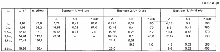
With increasing speeds vetropotokah samorazgona danger and its consequences increases. Thus, by reducing the number of specific speed Z = wCh R / v (with an increase in V) positive values of power coefficient C p is stored for ever higher speeds at speed V i of 15.0 m / s (20,25.30 m / s) v ~ and w. At the same time due to the increasing speed v ~ continues to increase capacity, even at low values of C p.
If w »(4 ... 5 w) n due to the increased speed of the peripheral part of the blade, the blade classic flow pattern is disturbed: there separated flows, which creates a" braking effect "and limits the speed of rotation of propeller over w» (4 .. .5) w n.
Under these conditions, as can be seen from the table, the presence of only one mechanical brake nominal power of the generator N fur 250,0 kW can guarantee the propeller stop at the propeller speed does not exceed 13.5 15.0 m / s.
In the dispersal of wind wheel braking power when the brake and increases. Growth inhibition capacity is proportional to the rotation speed increase, since the braking torque in the transmission is implemented - is constant.
The heat generated during operation of the mechanical brake determines its mode of operation as an emergency and short-term.
Consider braking mode propeller.
Current case.
The rotating wind-wheel loaded mechanical brake with N m 250.0 kW.
power supply from vetropotokah in braking mode is not taken into account.
The angular acceleration during braking (M t M nom transmission) ![]()
where J is the moment of inertia of the rotating masses of transmission and propeller, reduced to the low-speed shaft.
J 6,8 × 10 March (kg × s × 2 m)
Taking into account the time of the flywheel and the rotating elements of the transmission quantity J is increased by 1.5 times and is
J about 10.2 × 10 March (kg × s × 2 m).
The moment M t, developed by brake ![]()
(Hereinafter Consider the parameters to the low-speed shaft: if ![]() (Mechanical power)
(Mechanical power)
w n = 4.98 s -1. 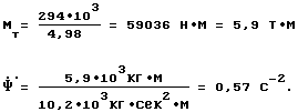
Deceleration Time propeller:
![]()
Said time t corresponds to the case in the absence of braking power supply from the propeller.
Obviously, for the case when entering the transmission of power from the propeller, exceeding the nominal, Annex M t removes only part of the problem: wind wheel under the influence of excess capacity D N, see FIG.. 2 continues to accelerate and can only be stopped by an additional application M m1, provided that the wind wheel is not gained power greater than the braking power by applying both braking moments M M m + m1.
The amount of energy released in the form of heat in the brake, can be defined as 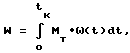
As the analysis of the motion during acceleration propeller with only one brake torque M t on w n to w = 2 w n under the influence of D N motion occurs at a variable angular acceleration J
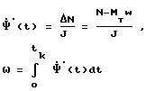
Therefore, as a criterion of a limiting condition, after which the accident could not be prevented, the conditions are selected to achieve the angular velocity of the wind wheel
w max = w 2 SG
Thus, when of not exceeding 2 w max = w nom possible to achieve aerodynamic power limits developed wind wheel.
This is illustrated in FIG. 3, which shows a wind wheel acceleration, starting from a speed exceeding the nominal on Dw = (4 ... 5%) w app moment M t, reducing the rate of acceleration of the wind wheel, speed up the achievement of its w max = w 2 rated at time t 2 and achieving deceleration by applying torque M m1. After reaching a stable process of braking the propeller and reducing its rotational speed is reached steady aerodynamic limiting his power (for effective braking and minimization of heat in the nacelle is necessary not only to inhibit but also to reduce the power received from the propeller and spent for braking, and this is achieved by aerodynamic means), whereby to achieve longer w = w SG may reduce the magnitude of additional braking torque developed by an electromagnetic brake.
Next, in the process of braking the rotating installation elements monotonically decrease the torque developed by the electromagnetic hysteresis brake, and to achieve the angular rotation of the propeller speed to rated speed 0,3.0,5 open hysteresis brake.
Signs of the proposed method in terms of:
- "Monotonic decrease the torque developed by an electromagnetic brake";
- "Off the electromagnetic brake to achieve the angular rotation of propeller speed to 0,3.0,5 rated speed", and in part used as an electromagnetic brake hysteresis generator braking mode ";
- reinforce the positive effects of the implementation of the combination of features set forth in the main claim, and made into additional points: Nos. 2, 3 and 4 of the appended claims.
The claimed method is essentially the first time to solve the practical problem quickly and efficiently (and multiple) stop propeller at all sorts of emergency situations, including the denial of the blades position control system mechanisms propeller throughout the range vetropotokah speeds, while allowing to realize the braking torque maximum value, objectively limited strength capability construction of wind turbines and available on a stand-alone wind turbines operating in automatic mode, the technical means and to create a stand alone wind turbines that do not require staff, even in emergency situations, because emergency algorithms wind turbine operation can be clearly defined, in this mode using the the claimed method.
In practice, this wind turbine for the Ministry of Defense facilities, remote farms, lighthouses, etc. Objects to which access is difficult.
Thus, the inventive method is progressive and its use creates a positive effect:
- improve the reliability and safety of wind turbines by preventing the development of an emergency in case of failure of the system turning propeller blades;
- increase the safety of operation of wind turbines;
- increase the resource of wind turbines by reducing the dynamic loads acting on the propeller blades, transmission, generator during braking modes, including emergency.
INFORMATION SOURCES
1. Author's certificate USSR N 1076617, cl. F 03 D 1/00 of 28/05/82.
2. Author's certificate USSR N 1325189, cl. F 03 D 7/04 of 07/01/76 - prototype.
3. The brake shoe. TAP Type 300 V2 PV 25% 220v, TU 24-1-1787-78.
4. Technical Proposal. Working to prevent vibrational modes of action when the unit is "Vetroen-250." TP.VET-250.03.94, M. Company "Obschemash-engineering", 1994.
CLAIM
1. A method for controlling a wind power installation, comprising the production of electricity when the generator setting on network restriction aerodynamic power developed by the wind wheel, and to stop the propeller, characterized in that in the generator mode during network malfunctions blade rotation system to install the rolling elements applied braking torque , the magnitude of the corresponding rated torque of the transmission, and then output the generator from the network and provide additional braking, turning a generator to additional hysteresis brake mode setting when the hysteresis braking point for a distance not exceeding the rated torque of the transmission, and the time t of additional braking torque application, on the one hand, selected from t i of (2 - 5) t, where t is the period of the lowest frequency of the blade vibrations of the wind wheel, and on the other - on the offensive conditions w max = 2 w nom, where w max maximum permissible speed propeller, w nom nominal propeller speed.
2. A method according to claim 1, characterized in that during braking the rotating installation elements monotonically decrease the torque developed by an electromagnetic brake.
3. A method according to claim 1, characterized in that the propeller while reducing the angular rotation speed to rated0,3 0,5 w disable rotation electromagnetic brake.
4. The method of claim. 1, characterized in that the electromagnetic brake is used as a generator in braking mode hysteresis.
print version
Publication date 02.04.2007gg
![]()

Comments
Commenting, keep in mind that the content and the tone of your messages can hurt the feelings of real people, show respect and tolerance to his interlocutors, even if you do not share their opinion, your behavior in terms of freedom of speech and anonymity offered by the Internet, is changing not only virtual, but real world. All comments are hidden from the index, spam control.