| Start of section
Production, amateur Radio amateurs Aircraft model, rocket-model Useful, entertaining |
Stealth Master
Electronics Physics Technologies Inventions |
Secrets of the cosmos
Secrets of the Earth Secrets of the Ocean Tricks Map of section |
|
| Use of the site materials is allowed subject to the link (for websites - hyperlinks) | |||
Navigation: => |
Home / Patent catalog / Catalog section / Back / |
|
INVENTION
Patent of the Russian Federation RU2147693
![]()
WIND POWER STATION
The name of the inventor: Artamonov Alexander Sergeevich
The name of the patent owner: Artamonov Alexander Sergeevich
Address for correspondence: 414052, Astrakhan, ul.Yablochkova, d.44, kv.57, Artamonovu A.S.
Date of commencement of the patent: 1998.06.01
The invention relates to wind power, namely to wind power plants. The technical result, consisting in increasing the coefficient of wind energy use and the specific power of the engine, expanding its application area, increasing the efficiency of gas generators used as a drive for a turbine of a wind turbine during periods of weak winds or in its total absence, is achieved due to the fact that in a wind power plant, A wind turbine with a turbine having a confuser for supplying an air flow, and an electric generator and an automation and control system according to the invention, the turbine is multistage, having guide nozzle apparatuses and an ejector, the ejector being multistage in the form of annular nozzles arranged coaxially with respect to each other Friend, and the last stage of the turbine is equipped with a bandage with blades with an aerodynamic profile.
DESCRIPTION OF THE INVENTION
The invention relates to wind power, namely to wind power plants.
A wind power plant is known, comprising a wind turbine mounted on a supporting structure with a turbine having a confuser for supplying air flow, and an electric generator and an automation and control system (see US, 4088419, 09.05.78, cl. F 03 D 7/00) adopted as a prototype.
The disadvantages of the known technical solution include the complexity of the design, the inadequate reliability of the aggregates included in it, and the low specific power of wind turbines as constituent elements of the wind power plant.
The technical result, consisting in increasing the coefficient of wind energy use and the specific power of the engine, expanding its application area, increasing the efficiency of gas generators used as a drive for a turbine of a wind turbine during periods of weak winds or in its total absence, is achieved due to the fact that in a wind power plant, A wind turbine with a turbine having a confuser for supplying an air flow, and an electric generator and an automation and control system according to the invention, the turbine is multistage, having guide nozzle apparatuses and an ejector, the ejector being multistage in the form of annular nozzles arranged coaxially with respect to each other Friend, and the last stage of the turbine is equipped with a bandage with blades with an aerodynamic profile.
The wind power plant additionally contains a multi-circuit turbojet engine as a source of gases for driving wind turbine turbines.
The nozzle of the combustion chamber of a multi-circuit turbojet engine is located in the outer and inner housing to form the last annular chamber whose walls are made of a dielectric material, the inner case having an electrode on one side and a branch for supplying a concentrated aqueous solution of a strong electrolyte to the placed electrolyte In it auger.
The automation and control system is made in the form of a multi-storey tower.
The outer surface of the last stage of the annular nozzles is provided with a visor.
The windmill is equipped with a rotary support mechanism.
The generator is equipped with a reducer.
The blades of the last stage of the multi-stage turbine are located in the tapering part of the first stage of the ejector.
 |
 |
 |
 |
 |
 |
 |
 |
In Fig. 1 shows a wind turbine (longitudinal section) with an ejector, a multi-stage turbine, and transmission of rotation from the turbine shaft through a conical transmission to a vertical shaft;
In Fig. 2 - longitudinal section of the windmill with an ejector and a deflector;
In Fig. 3 - multi-storey supporting structure - a tower with wind turbines placed on each floor with electric generators and reducers installed on the underlying sublevels;
FIG. 4 is a diagram of a tower and wind turbines on a swing beam; FIG.
In Fig. 5 - multi-circuit turbojet engine (longitudinal section);
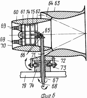
In Fig. 6 - wind turbine with gas generators, turbines of opposite rotation and support mechanism for the possibility of turning on the wind of the engine;
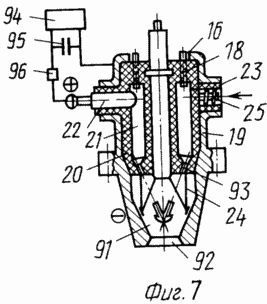
In Fig. 7 - nozzle of the combustion chamber of a multi-circuit turbojet engine (longitudinal section) and schematic diagram of an electric pulse generator;
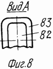
In Fig. 8 is a view A of FIG.
The wind power plant comprises a wind turbine 2 (shown in FIG. 3) mounted on a supporting structure 1 (FIG. 3) with a turbine 3 (first stage) (FIG. 1) having an air supply inlet confuser 4 (FIG. 1), and an electric generator 5 (FIG. .3) and an automation and control system in the form of a multi-storey tower 6 (FIG. 3), the turbine 3 being multistage, having guide nozzle apparatuses 7, 8 (FIG. 1) and an ejector 9 (FIG. 1), the ejector 9 is multistage in the form of annular nozzles 10 (FIG. 1) arranged coaxially with respect to each other, and the last stage 11 of the turbine 3 is provided with a shroud 12 with blades having an aerodynamic profile.
The station further comprises a multi-circuit turbojet engine with a casing 13 as a source of gases for driving the first and second stages 14 and 15 of the turbine of the windmill 2.
The nozzle 16 of the combustion chamber 17 of the multi-turbojet engine 13 is located respectively in the outer and inner housings 18 and 19, with the latter forming an annular chamber 20 whose walls are made of a dielectric material 21, the inner case 19 having, on the one hand, an electrode 22, and on the other side - branch pipe 23 for supplying a concentrated aqueous solution of a strong electrolyte 24 with a screw 25 disposed therein.
The outer surface of the last stage of the annular nozzles 10 is provided with a peak 26.
The wind turbine 2 is provided with a rotational support mechanism 27.
The electric generator 5 is provided with a gear 28.
The blades of the last stage 11 of the multi-stage turbine 3 are located in the tapered portion 29 of the first stage 30 of the ejector 9.
The first stage of the turbine 3 and the last stage 11 of the turbine 3 have a shaft 31 on which the rectifying apparatus 32 is located.
An annular nozzle 10 is fixed through the headers 33 to form an ejector 9 having an inlet annular opening 34.
The rotation transmission from the shaft 31 of the turbine 3 is effected via a conical transmission 35 to the shaft 36, which transmits the rotation to the reduction gear 28 and from it to the generator 5.
In turn, the annular nozzle 10 is mounted on a pivoting support mechanism 27 on which support rollers 37 are mounted along the perimeter supported on the inner surface of the support ring 38 located on the beams 39 of the multi-storey tower 6. The tower 6 is constructed as a multi-storey structure with main floors 40 And lower levels 41 for placing auxiliary mechanisms of wind turbines 2 and electric generator 5. Tower 6 is supported by foundations 42.
The operating blades of the first stage of the turbine 3 and the last stage 11 (FIG. 1) are mounted on the drum 43.
In the embodiment of the wind turbine 2, the guiding apparatus 45, 46 (FIG. 2) and the turbines 47 and 48 (FIG. 2) are located in its housing 44, the latter of which has an outer ring 49 with blades 50 fixed thereon located in the critical section of the ejector 9, comprising a ring 51 and a housing 44.
The ejector 9 is provided with two inlet annular apertures 52 and 53 and headers 54, 55 disposed between the housing 44 and the ring 56 between the rings 56 and 51.
The canopy 26 allows vortex formation behind the outlet opening 57 of the ejector 9 with a detached flow of air flow around the wind turbine 2.
Engines 58 are suspended to a swing beam 59.
The wind turbine variant (see Figure 6) consists of a housing 60, a directing nozzle 61, a first and a second stage 14, 15 (Fig.6) of a turbine, a rectifying apparatus 62, an annular nozzle 63 of an ejector 9 fixed by means of a kerchief 64 on the body 60, two bevel gears 65 and 66 with rotation from them to the reduction gear 28 and the generator 5 by means of two vertical shafts 67, 68.
The housing 60 is a venturi nozzle in the section and consists of two multi-circuit turbojets 69 with an inlet 70.
The motor 69 is mounted on a pivoting device 71 having brackets 72 with support rollers 73 freely movable when the motor 69 rotates along the inner surface of the support ring 74 located on the beams 39 of the tower 6.
The multi-circuit turbojet engine (FIG. 5) consists of a casing 13, a compressor 75, combustion chambers 17 with a common nozzle 76. A turbine 77 with a guide 78 and a straightening 79 apparatus is located in the third engine circuit.
Inside the body 13, in addition to the nozzle 76, nozzles 80, 81, 82, 83 are successively placed one after the other into which atmospheric air is injected through the suction holes 84, 85, 86, 87. The shaft 88 of the turbine 77 and the compressor 75, the starting motor 89 are installed in front of the compressor 75 in the casing 90.
The nozzle 16 of the combustion chamber 17 comprises an explosive chamber 91 with an opening 92. The annular chamber 20 comprises nozzles 93 in the end portion. The nozzles 16 are installed in the combustion chambers 17 and connected to an electric pulse generator consisting of a constant voltage source 94, a capacitor 95 and a device switching device 96.
VETROELECTRIC POWER STATION WORKS AS FOLLOWING
At a wind speed of 5.5-6.0 m / s and setting all wind turbines 2 to the wind, the incoming airflow in the confuser 4 increases its speed and through the guiding devices 7, 8 enters the working blades of the stages 11 of the turbine 3 installed on the drum 43 , Mounted on a shaft 31, which drives a shaft 36, a reduction gear 28 and a generator 5 through a conical gear 35.
When the direction of the wind changes, each wind turbine 2, according to the height of the tower 6, which is an autonomous power source with electric power transmission from all windmills 2 to the common wind power station, is set to the wind due to the difference in the dynamic wind pressure on the side surfaces of the wind turbine 2 and the annular nozzle 10.
The large geometric dimensions of the ring 10, as compared to the wind turbine 2, provide a large difference in the forces of the dynamic wind pressure and rapid rotation of the motors 2 to the wind by moving the rollers 37 along the inner surface of the support ring 38.
The increase in the speed of the air flow by half due to the tapering confuser 4 and the guide apparatus 7 on the blades of the turbine 3 of the first stage provides an eightfold increase in the power of the windmill 2, since it is known that the amount of energy contained in the wind is proportional to the area of the turbine section and the wind speed to the third power, And the operation of the jet engine of the wind turbine 2, when air enters it through the inlet 34, allows increasing the output speed from the first stage of the turbine 13 to a numerical value of approximately equal to the speed of the air flow on the blades of the first stage of the turbine 3 and to increase the total wind turbine power by 1.8-2 Times.
The multi-circuit turbojet engine works as follows: the starting motor 89 rotates the compressor 75 from which the compressed air enters the combustion chambers 17, mixes with the fuel coming from the injectors (not shown in the drawing) and ignited by the ignition device, after which the combustion is carried out in Continuous mode. Simultaneously, the compressed air from the compressor 75 is withdrawn and washed outside the combustion chamber 17, providing a normal temperature of their walls, and mixed with the combustion products flowing from the chambers 17. A mixture of air and gases with a temperature of 1800-2000 ° C flows out of the common nozzle 76 and sucks the atmospheric Air through the openings 84, 85, followed by acceleration in the nozzles 80, 81, from which the air-gas mixture at a lower speed and temperature sucks air through the next holes 82, 83, and at a lower temperature and speed, enters the turbine 77 which rotates the compressor 75.
CLAIM
1. A wind power plant comprising a wind turbine mounted on a supporting structure with a turbine having a confuser for supplying an air flow, and an electric generator and an automation and control system, characterized in that the turbine is multistage, having directing nozzle apparatuses and an ejector, the ejector being multistage in the form of annular Nozzles placed coaxially with respect to each other, and the last stage of the turbine is equipped with a band with blades having an aerodynamic profile.
2. The station of claim 1, further comprising a multi-circuit turbojet engine as a source of gases for driving wind turbine turbines.
3. A station according to claim 2, characterized in that the burner nozzle of the multi-circuit turbojet engine is located in the outer and inner housing to form the last annular chamber whose walls are made of a dielectric material, the inner case having an electrode on one side and, on the other Sides - a branch pipe for supplying a concentrated aqueous solution of a strong electrolyte with a screw placed in it.
4. Station according to claim 1, characterized in that the automation and control system is made in the form of a multi-storey tower.
5. A station according to claim 1, characterized in that the outer surface of the last stage of the annular nozzles is provided with a visor.
6. A station according to claim 1, characterized in that the windmill is provided with a pivoting support mechanism.
7. A station according to claim 1, characterized in that the electric generator is provided with a reducer.
8. A station according to claim 1, characterized in that the blades of the last stage of the multi-stage turbine are located in the tapering part of the first stage of the ejector.
print version
Date of publication 11.01.2007gg


Comments
Commenting on, remember that the content and tone of your message can hurt the feelings of real people, show respect and tolerance to your interlocutors even if you do not share their opinion, your behavior in the conditions of freedom of expression and anonymity provided by the Internet, changes Not only virtual, but also the real world. All comments are hidden from the index, spam is controlled.